Thermal oil systems run hot — typically 150 to 350 °C — and that heat breaks most flow meters long before it breaks the piping. A vortex flow meter is one of the few instruments that survives this duty with no moving parts, no wetted elastomers, and no frequent recalibration. This guide explains why the vortex principle suits heat transfer oil, how to size the meter correctly for your hot oil line, and what to get right at installation.
Why Thermal Oil Flow Measurement Is Difficult?
Thermal oil (heat transfer fluid) is not water, and it does not behave like it. Three properties make it one of the harder liquids to meter accurately:
High operating temperature.
1. Most hot oil systems circulate between 150 and 350 °C. At that temperature, electronics degrade, elastomers fail, and any instrument with wetted plastic or rubber parts is out of the question.
Density and viscosity shift sharply with temperature.
2. A hot oil loop can swing 100 °C between cold startup and full load. Density changes alter the relationship between volumetric flow and the energy actually delivered to the process; viscosity changes move the meter's low-flow limit.
Low system pressure.
3. Hot oil circuits typically run at modest pressure (many at or below PN16). At high temperature, the fluid's vapor pressure rises, so cavitation margin and vapor handling deserve real attention — not just a line item on the datasheet.
Add the fact that the plant wants a corrected volume or mass figure for burner control and energy accounting — not a raw velocity reading — and you have a genuine metering problem, not a shopping decision.
Why a Vortex Flow Meter Fits Thermal Oil Service
A vortex flow meter works on the Kármán vortex street principle. A bluff body (the shedder) is placed across the flow; fluid alternately sheds vortices from either side of it; the shedding frequency is proportional to flow velocity:
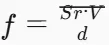
where f is the vortex shedding frequency (Hz), V the flow velocity (m/s), d the shedder width (m), and Sr the Strouhal number — essentially constant (≈ 0.17–0.18) over a wide Reynolds range and independent of fluid properties.
Because frequency, not force or heat, carries the measurement, the vortex meter brings structural advantages that matter specifically in hot oil duty:
Requirement in thermal oil service | Vortex meter answer |
No wetted moving parts to fail | Shedder and sensor are solid stainless steel — no rotor, no gears, no bearings |
Heat tolerance | Standard temperature grades: −20 to 250 °C and −20 to 350 °C |
Corrosion and dirt resistance | SS304 body standard, SS316L on request; no internal pockets or dead zones |
Wide turndown | 1:6, 1:10 or 1:15, so one meter covers startup and full-load flow |
Low pressure drop | Resistance coefficient Cd = 2.2 — gentle on low-pressure hot oil circuits |
Medium compatibility | Liquids, gases, steam and thermal oil are all listed media for the CG series |
CG Series Specifications for Hot Oil Lines
The table below summarizes the parameters that matter when you specify a vortex meter for a heat transfer oil application (CG series):
Parameter | Specification |
Nominal diameters | DN15 to DN300 |
Media | Liquid, gas, steam, thermal oil |
Medium temperature grades | −20 to 250 °C; −20 to 350 °C |
Pressure rating | PN16 (higher ratings available on agreement) |
Body material | SS304 standard; SS316L on request |
Accuracy classes | 1.0 / 1.5 / 2.5 |
Turndown | 1:6 / 1:10 / 1:15 |
Outputs | Pulse, 4–20 mA, RS485 (Modbus RTU/ASCII), HART |
Power | 3.6 V battery or DC 24 V |
Explosion protection | Exd II CT6 Gb |
Ingress protection | IP65 standard; IP68 on request |
Display | Optional full-dot-matrix LCD (instantaneous flow, total, temperature, pressure) |
For thermal oil, the 350 °C grade is the one to plan around. A heat transfer fluid system that is designed for 300–320 °C outlet temperature leaves a comfortable margin; a system pushing 340 °C does not, so confirm the maximum sustained temperature (not just the setpoint) before ordering.
Sizing a Vortex Meter for Thermal Oil
The liquid flow ranges in the manual are calibrated on water at 4 °C (ρ₀ = 1000 kg/m³). Thermal oil is lighter and more viscous, so you cannot pick a size directly from the water table — the effective low-flow limit must be corrected for both density and viscosity.
Density correction. The lower limit scales inversely with density:

Viscosity correction. The viscosity-limited lower limit is:

where ν is the kinematic viscosity (m²/s) and D the pipe inner diameter (mm). Take the larger of the two corrected values as the effective lower limit.
Worked example (DN50). Assume a synthetic thermal oil at 300 °C with ρ = 850 kg/m³ and ν = 2 × 10⁻⁶ m²/s (2 cSt). The water-calibrated range for DN50 is 3.5–35 m³/h:
Density-corrected limit: 3.5 × 1000 / 850 ≈ 4.1 m³/h
Viscosity-corrected limit: 6 × 2 × 10⁻⁶ × 50 × 10⁴ = 6.0 m³/h
Effective lower limit: 6.0 m³/h — almost double the water-table figure
The practical rule: for thermal oil, size the meter so that your minimum sustained operating flow sits comfortably above the corrected lower limit. If your minimum flow is too low for the pipe size, go down one nominal diameter rather than accepting an oversized meter that will read nothing at low rates.
Upper limit and cavitation. Liquid velocity should stay at or below 6 m/s. And because hot oil has a high vapor pressure, verify the cavitation condition from the manual:

where P is the line pressure at the meter, ΔP the meter pressure loss at operating flow, and Ps the fluid vapor pressure. If the margin is insufficient at maximum temperature, a larger diameter (lower velocity, lower ΔP) or a higher operating pressure is the fix.
Temperature and Pressure Compensation: The Accuracy Factor
A bare vortex meter reports actual volume at line conditions. For thermal oil, that is not the number your burner control or energy balance needs — density can vary several percent across a normal operating window, which means the same volume flow carries noticeably different heat.
The CG series converter supports temperature and pressure compensation directly:
Temperature input:
Pressure input:
Output:
compensated instantaneous flow, total, temperature and pressure over 4–20 mA, pulse and RS485 (Modbus RTU) — registers for instantaneous flow, total, temperature and pressure are available for DCS/PLC integration
For a thermal oil application, order the temperature and pressure compensated version and connect the RTD to the flow meter body's thermal well or the pipe's temperature tap. This converts the measurement into mass or corrected volume and removes the biggest systematic error in hot oil metering.
Installation Best Practices for High-Temperature Lines
Vortex meters are sensitive to flow profile and heat — both of which are exactly where thermal oil installations go wrong. Follow these rules:
Respect straight-run requirements.
1. The vortex meter needs the upstream and downstream straight pipe lengths specified in the manual's installation figure; the flow profile upstream of the shedder determines accuracy. Never install a control valve upstream — the manual requires the regulating valve to sit at least 10D downstream of the meter.
Match pipe and meter bores.
2. Upstream and downstream pipe inner diameter Dp must satisfy 0.98·Db ≤ Dp ≤ 1.05·Db (Db = meter bore), with concentricity within 0.05·Db.
Keep gaskets out of the flow.
3. Sealing gaskets must not protrude into the pipe; their inner diameter should be 1–2 mm larger than the meter bore.
Protect the converter from conducted heat.
4. The electronics inside the converter housing should not exceed about 70 °C. Insulate the pipe and the meter body, but leave the converter neck exposed so heat conducts away — insulating the whole head is the classic cause of premature electronics failure on hot oil meters.
Install for a full pipe.
5. In vertical or inclined lines, liquid must flow from bottom to top so the measuring tube stays full. If the oil may contain small amounts of gas, mount the meter at a low point in the line.
Locate temperature and pressure taps correctly.
6. When the meter uses external compensation, place the pressure tap 3–5D downstream and the temperature tap 6–8D downstream of the meter.
Use proper high-temperature gaskets and flange hardware.
7. With flange connections, confirm the flange rating (PN class) matches the operating temperature — standard flanges per GB/T 9119 are listed in the manual, and ANSI/European standards are available on request.
Common Mistakes and How to Avoid Them
Mistake | Consequence | Fix |
Sizing from the water table without density/viscosity correction | No signal or unstable reading at low oil flow | Apply the correction formulas; if needed, step down one diameter |
No temperature/pressure compensation | Several percent error in energy accounting | Order the compensated version with PT100/PT1000 + pressure transmitter |
Insulating the converter head | Electronics overheat (limit ≈ 70 °C), premature failure | Insulate the body only; keep the neck exposed |
Control valve upstream of the meter | Disturbed flow profile, erratic readings | Move the valve ≥ 10D downstream |
Meter partially empty (gas pockets) | Erratic output, over-reading | Bottom-to-top flow in vertical lines, mount at low point |
Ignoring vapor pressure at high temperature | Cavitation, loud noise, unstable readings | Check P > 2.6ΔP + 1.25Ps; enlarge diameter or raise pressure |
FAQ
Q: Can a vortex flow meter measure thermal oil?
A: Yes. Thermal oil is an explicitly listed medium for the CG series vortex flow meter, alongside liquids, gases and steam. With SS304/SS316L wetted parts and no moving components, it is well suited to high-temperature heat transfer fluid duty.
Q: What is the maximum temperature for a vortex flow meter?
A: The standard temperature grades are −20 to 250 °C and −20 to 350 °C. For thermal oil systems, choose the 350 °C grade and verify the maximum sustained oil temperature. Keep the converter electronics below about 70 °C through proper insulation design.
Q: Do I need temperature and pressure compensation for thermal oil measurement?
A: For corrected volume or mass flow — the number energy accounting needs — yes. Thermal oil density changes several percent across a normal operating window. The CG series supports PT100/PT1000 temperature input and absolute/gauge pressure input for automatic compensation.
Q: What accuracy can I expect from a vortex flow meter on thermal oil?
A: Accuracy classes of 1.0, 1.5 and 2.5 are available, with turndown from 1:6 up to 1:15. Accuracy depends on correct sizing (so the operating flow stays above the corrected lower limit) and on compensation for density changes.
Q: Why does my vortex flow meter show no signal at low thermal oil flow?
A: The flow is probably below the effective lower limit, which for thermal oil is higher than the water-calibrated table value due to lower density and higher viscosity. Apply the density and viscosity correction formulas, or select a smaller meter diameter.
Q: Can vortex flow meters be used in explosive areas?
A: Yes. The CG series carries Exd II CT6 Gb explosion protection and IP65 (IP68 on request) ingress protection, covering common hazardous-area classifications in thermal oil plants.
Ethan Liu
Ethan Liu is JUJEA's technical content specialist, translating complex sensor integration and industrial automation concepts into practical insights for engineers, system integrators, procurement professionals, and decision-makers worldwide.


 한국어
한국어 français
 Deutsch
 Español
 italiano
 русский
 português
 العربية
 tiếng việt
 čeština