This is the LC Series manual as a page instead of a file. The same content, the tables as real tables, so the model codes, the flow range for your viscosity and the pulse equivalent for your counter are searchable and copyable — and so a typo in the field can be checked without downloading a PDF and scrolling to page nine.
What this page covers: how the eight model codes differ (body material and viscosity class), the flow range for every bore from DN10 to DN200 across four viscosity bands, the accuracy and pressure classes, the transmitter and wiring options including the pulse equivalent table, the LB07 4–20 mA settings, the installation rules that decide whether the meter reads right, and the fault table from section XI.
Revision: based on the LC Series manual, dossier 20260731. The original PDF is linked at the end.
The Eight Model Codes: Two Variables, Not Eight Products
There are not eight instruments here. There are two choices — what the body is made of, and whether the meter is built for ordinary or high-viscosity liquid — plus a temperature variant of each.
Name | Iron casting | Cast steel | High-temp iron casting | High-temp cast steel | High-viscosity iron casting | High-viscosity cast steel | Stainless steel | Transmitter |
Model | LC-A | LC-E | LC-TA | LC-TE | LC-NA | LC-NE | LC-B | LC-13 |
Body | iron casting | cast steel | iron casting | cast steel | iron casting | cast steel | stainless steel | various |
Gears | iron casting | iron casting | iron casting | iron casting | iron casting | iron casting | stainless steel | various |
Reading the table:
LC-A and LC-E are the general-purpose pair. Choose between them on pressure and on the corrosion question, not on flow range — the ranges are the same.
LC-TA and LC-TE are the same bodies with a radiator between the transmitter and the counting mechanism. That is what extends the working temperature to 200 °C on the pointer version.
LC-NA and LC-NE are the high-viscosity pair. The measuring chamber and gearing tolerate liquids up to 2000 mPa·s, which the general-purpose models do not cover.
LC-B is the stainless steel version, and the manual is explicit about when to take it: if the tested liquid is chemically corrosive, a flowmeter of stainless steel should be selected.
LC-13 is not a body at all — it is the transmitter option, covered below.
Function Codes: What the Counter Adds
The suffix after the model is the counter and output configuration. It decides what you can read at the meter, and whether you need a separate transmitter at all.
Function | A1 | A | Z | 13 | J1 | ELZ |
Pointer, cumulative six rollers | ● | ● |
|
|
|
|
Pointer, cumulative six rollers, resettable | ● | ● | ● |
|
|
|
Pointer, with message | ● |
|
|
| ● |
|
Single message (signal output) |
|
|
| ● |
|
|
LCD display — instantaneous, cumulative, 4–20 mA, pulse, RS485 |
|
|
|
|
| ● |
In practice:
A1 / A / Z are mechanical pointer counters. Z adds a reset. If the installation is a filling point where the operator zeroes between batches, this is the one.
13 gives a signal output only.
J1 is the pointer counter with a message function.
ELZ is the LCD version carrying instantaneous flow, cumulative total, 4–20 mA, pulse and RS485 in one head. For anything that has to reach a PLC or a batch controller, this is the code to specify, and it removes the need for a separate LC-13 transmitter.
Flow Range by Bore and Viscosity
This is the table most enquiries get wrong. The same bore measures a different range depending on how thick the liquid is, and the high-viscosity models are not simply the same numbers shifted.
Standard and high-temperature models (LC-A / LC-E / LC-TA / LC-TE), accuracy class 0.5, flow in m³/h:
DN (mm) | Viscosity 0.6–2 mPa·s | Viscosity 2–200 mPa·s |
10 | 0.2 – 0.4 | 0.08 – 0.4 |
15 | 0.6 – 1.5 | 0.3 – 1.5 |
20 | 0.8 – 3 | 0.6 – 3 |
25 | 1.2 – 6 | 0.8 – 6 |
40 | 5 – 15 | 3 – 15 |
50 | 6 – 24 | 4 – 24 |
65 | 10 – 40 | 8 – 40 |
80 (light) | 10 – 40 | 8 – 40 |
80 (heavy) | 15 – 60 | 10 – 60 |
100 | 30 – 100 | 15 – 100 |
150 | 45 – 190 | 34 – 190 |
200 | 68 – 340 | 56 – 340 |
High-viscosity models (LC-NA / LC-NE / LC-NB), accuracy class 0.5, flow in m³/h:
DN (mm) | Viscosity 200–1000 mPa·s | Viscosity 1000–2000 mPa·s |
10 | 0.04 – 0.3 | 0.03 – 0.2 |
15 | 0.2 – 1.0 | 0.1 – 0.7 |
20 | 0.4 – 2.1 | 0.25 – 1.5 |
25 | 0.6 – 4.2 | 0.6 – 3 |
40 | 2.1 – 10.5 | 1.0 – 7.5 |
50 | 2.4 – 16.8 | 2 – 12 |
65 | 6 – 28 | 4 – 20 |
80 (light) | 6 – 28 | 4 – 20 |
80 (heavy) | 8 – 42 | 6 – 30 |
100 | 10 – 70 | 10 – 50 |
150 | 27 – 133 | 19 – 95 |
200 | 48 – 238 | 34 – 170 |
Three things worth noticing:
Thicker liquid lowers the minimum, not the maximum. On DN25 the top end is 6 m³/h either way, but the bottom moves from 1.2 to 0.8 m³/h between the thin and thick columns. That is the volumetric-efficiency effect: a slow-turning gear with viscous liquid seals better than a slow-turning gear with water.
DN50 and DN80 come in light and heavy types. The heavy type has a larger range at the same bore, so "DN80" alone is not a specification.
The 0.2 % class has its own range table. Those numbers differ from the 0.5 % table above and are printed separately in the manual. Do not size from this page if you are ordering the high-precision version.
Read these tables as a shortlist, not a specification — confirm the bore against your minimum and maximum flow before ordering.
Accuracy, Pressure and Temperature
Property | LC-A | LC-E | LC-B |
Nominal pressure | 1.6 MPa | 1.6 / 2.5 / 4.0 / 6.3 MPa | 1.6 / 2.5 / 4.0 / 6.3 MPa |
Accuracy | 0.5 % standard; 0.2 % high-precision version | same | same |
Temperature depends on the counter, not the body:
Counter | Temperature range |
Pointer, conventional | −20 ~ +80 °C |
Pointer, high temperature | −20 ~ +200 °C |
LCD, conventional | −20 ~ +60 °C |
LCD, high temperature | −20 ~ +150 °C |
So a 180 °C oil line needs two selections, not one: the TA or TE body and the high-temperature pointer counter. An LCD head on that line is only rated to 150 °C.
The manual publishes an error and pressure-loss curve for the 0.5 class across four media — aviation gasoline at 0.7 mPa·s, water at 1 mPa·s, light diesel at 5 mPa·s and transformer oil at 20 mPa·s — with the error band held inside ±0.5 % and pressure loss rising with both flow and viscosity. If pressure loss matters on your line, read that curve before choosing the bore: it is the reason a small bore is not automatically the cheap answer.
Transmitters and Outputs
LC-13 transmitter — the body-and-transmitter combination for remote display, control and recording:
Parameter | Value |
Outputs | MF: 4–20 mA; GF: photoelectric pulse |
Supply | DC 12 V or DC 24 V |
Pipe connection | flange JB/T79~82—1994 |
Transmission distance | 0 – 1000 m |
Electrical accuracy | ±1 pulse |
Ambient temperature | −10 ~ +60 °C |
GF-IGF-II pulse transmitter — the standalone pulse head matched to the LC series:
Parameter | Value |
Supply | DC 12 / 24 V |
Transmission distance | 0 – 1000 m |
Electrical accuracy | ±1 pulse |
Ambient temperature | −10 ~ +65 °C |
Explosion-proof grade | ExdIIBT4 |
Pulse equivalent: what to type into the counter
If you are pairing the meter with an A1 or J1 counter, the pulse equivalent is fixed by bore — it is not a free parameter, and getting it wrong scales every total by a constant.
DN (mm) | L per pulse | Pulses per second at full scale |
10 | 0.004 | 27.77 |
15 | 0.04 | 10.41 |
20 | 0.04 | 20.83 |
25 | 0.04 | 41.67 |
40 | 0.4 | 10.41 |
50 | 0.4 | 16.67 |
65 / 80 (light) | 0.4 | 27.77 |
80 (heavy) | 0.4 | 41.67 |
100 | 0.4 | 69.44 |
150 | 0.4 | 52.78 |
200 | 0.4 | 94.44 |
Wiring: Two-Wire and Three-Wire 4–20 mA
The transmitter head terminates on four numbered positions: 1: V+, 2: SO, 3: I+, 4: GND. Which of them you use depends on whether the loop is two-wire or three-wire.
Mode | Terminals used | Wiring |
Two-wire 4–20 mA | V+, GND | V+ to 24 V positive; GND to the positive end of the loop |
Three-wire 4–20 mA | V+, I+, GND | V+ to 24 V positive; I+ to the current output positive; GND to the 24 V negative |
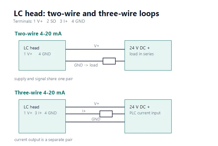
Two-wire uses the supply pair as the signal pair; three-wire keeps the current output separate. The load goes in series in both cases.
Setting the LB07 4–20 mA converter
The LB07 head carries five parameters. They are reached with the two keys — M (left) and S (right) — and they are the whole commissioning procedure:
Parameter | Meaning | Range |
P00 | Coefficient of flowmeter (pulse equivalent) | 0.00001 – 9.99999 L/pulse |
P01 | Maximum flow (range) | m³/h, two decimals |
P02 | Minimum flow — sets the reset time | m³/h, two decimals |
P03 | 4 mA trim | larger value, greater current |
P04 | 20 mA trim | larger value, greater current |
In the running state, long-press S to display P00 and its value, then short-press S to step to P01, P02 and so on. Short-press M to enter edit, S to increment, M to move to the next digit. To save, hold S until the display flashes "SaUEd" and returns to the running state — if you do not see SaUEd, nothing was written.
While the accumulation is displayed, a short press of S resets the total. The manual notes this is the function used to adjust for pulse loss, which is worth knowing before someone presses it by accident.
Installation: The Rules That Decide Whether It Reads Right
These come from section IX of the manual, and most field complaints trace back to one of them.
Fit the matching filter before the meter, outlet to the meter inlet, with the arrow on both bodies pointing with the flow.
If the liquid carries gas, fit a gas elimination filter upstream. The manual treats this as a separate device, not a setting.
The oval gears must sit horizontally — the dial disc perpendicular to the ground — whether the pipe runs horizontally or vertically. This is the rule most often broken on vertical runs.
If the dial is awkward to read, rotate the counter 90° or 180°. It is designed to be turned.
On a new meter, push the elliptical gear a few times from the outlet with a bamboo stick. If it does not move, soak in diesel. (Factory inspection can leave sediment.)
A flow control valve at the inlet, an open/close valve at the outlet, and open slowly — sudden opening produces water hammer and a spike the gears will remember.
Flush the new pipeline before fitting the meter, using a spool piece in its place, so welding slag and debris never reach the measuring chamber.
Never test a cast iron or cast steel meter with water. This is stated flatly in the manual, and it is the reason the factory calibrates on diesel.
Do not exceed the technical maximum flow — run at 50–80 % of it. At the top of the range the error curve opens up and the pressure loss is at its steepest.
Error Calculation and Adjustment
The basic error is calculated against a volumetric standard:
E = (V_measured − V_actual) / V_actual × 100 %
Where V_measured is the meter reading and V_actual is the standard after correction. A positive result means the meter runs fast; a negative result means it runs slow.
The adjustment is mechanical, not electronic: a pair of adjusting gears in the counter changes the transmission ratio, which shifts the error curve into a new coordinate system. The standard pair is 38/35; the manual also references 41/38 and 40/37. Two cautions straight from the text:
Error adjustment cannot change the flow characteristics of the meter — it moves the curve, it does not flatten it.
If the error exceeds 1 %, replacing the gear pair is not the fix. At that point the double-layer gear is worn and should be replaced, then the meter recalibrated.
Common Faults
Reproduced from section XI. This is the part of the manual worth having on a phone in the plant rather than a laptop in the office.
Fault | Cause | Action |
Oval gear does not rotate | Debris in the pipeline; damaged filter letting solids into the chamber | Remove the meter and the line, clean the chamber, repair or replace the filter |
Leakage at the axial sealing coupling | Packing worn or dry | Tighten the gland or replace the packing, refill sealing oil |
Pointer rotation unstable | Loose pointer or washer; stiff rotating parts | Retighten, free the rotating parts |
Small-flow error too negative | Elliptical gear catching the chamber wall — bearing wear or chamber deformation | Replace bearings, repair the chamber and gear, ensure clearance, calibrate after repair |
Error changes a lot | Large flow pulsation, or gas in the liquid | Reduce pulsation, add a gas separator |
Error too large but within ±1 % | Clearance changed after service | Recalibrate and adjust |
No signal when transmitting | Transmitting block position wrong; polarity reversed | Move the block left/right; rewire — + to the red wire, − to the black wire |
On a 0.2 level meter the manual adds a tolerance note: after service, the change between maximum and minimum should not exceed ±0.17 %.
What to Send When Ordering
The manual's ordering list, condensed to what actually decides the build:
Model, specification and material — or the liquid, and let the material follow.
Medium temperature, working pressure and flow range.
Medium viscosity, or the medium name if the viscosity is unknown. This is the one that changes the model family.
Special requirements — remote transmission, explosion protection.
Flange standard, if it is not JB/T79~82—1994.
If the viscosity is missing, the quotation will be a guess between two different products.
Download the Original Manual
LC Series Oval Gear Flowmeter — instruction manual (PDF)
Two notes from section XII that are easy to miss: the instrument is tested with diesel before dispatch according to JJG667-2010 Liquid Volumetric Flowmeter, and the matching filter is an independent product priced separately — it is not part of the meter.
FAQ
What is the difference between LC-A, LC-E and LC-B? Body and gear material. LC-A is iron casting at 1.6 MPa; LC-E is cast steel available to 1.6, 2.5, 4.0 and 6.3 MPa; LC-B is stainless steel, which the manual specifies for chemically corrosive liquids. Their flow ranges are the same for a given bore.
What does the ELZ code mean? The LCD counter configuration: instantaneous flow, cumulative total, 4–20 mA, pulse and RS485 in one head. Specifying ELZ removes the need for a separate LC-13 transmitter.
Why does the manual say not to test the meter with water? Because cast iron and cast steel bodies and gears corrode. The factory calibration is done on diesel under JJG667-2010, and a water test on a carbon steel meter leaves the chamber rusting before it is ever installed.
Which flow range applies to DN25 with 500 mPa·s oil? Use the high-viscosity table: DN25 spans 0.6–4.2 m³/h in the 200–1000 mPa·s band. The general-purpose table does not cover 500 mPa·s at all, so the model family changes, not just the bore.
My reading is low at small flow — what is worn? The manual's diagnosis is that the elliptical gear is catching the chamber wall, from bearing wear or a deformed measuring cavity. Replace the bearings, repair the chamber and gear, confirm the clearance, then recalibrate. Do not correct it with the adjusting gears.
Where in the range should the meter normally run? Between 50 % and 80 % of maximum flow. At the top of the range the error curve opens out and pressure loss is steepest; at the bottom the gear turns too slowly for the viscosity to seal the clearances.
References
LC Series Oval Gear Flowmeter instruction manual, sections II–XIII.
JJG667-2010, Liquid Volumetric Flowmeter — the verification regulation the factory tests against.
JB/T79~82—1994 — flange standard used on the LC-13 transmitter connection.
If you are selecting between the general-purpose and high-viscosity families and the viscosity figure is uncertain, send the medium name and the temperature and we will come back with the family first, the bore second.
Ethan Liu
Ethan Liu is JUJEA's technical content specialist, translating complex sensor integration and industrial automation concepts into practical insights for engineers, system integrators, procurement professionals, and decision-makers worldwide.


 한국어
 français
 Deutsch
 Español
 italiano
 русский
 português
 العربية
 tiếng việt
 čeština