A clamp-on meter out of band by 5 % is not a meter that is slightly wrong. On a 200 m³/h line it is 10 m³/h — 240 m³ a day that never reaches a balance sheet, a tariff or a batch record, and the instrument will not alarm because it has no way to know. The three faults behind most service calls — no signal, no communication, phantom flow — are separated by four numbers the transmitter already displays.
Short answer: open menu M90 before you change anything. Signal strength below 60 means the acoustic path is broken and no parameter will fix it. A transmission-time ratio outside 97–103 % means the pipe data and the sensor spacing disagree. Once both are inside range, the fault is in the zero point, the low-flow cut-off or the communication settings — not in the installation.
If you are specifying rather than repairing: the same three numbers predict whether a clamp-on installation will still be accurate in three years. Read them at commissioning, not only at breakdown.
Read M90 Before You Touch Anything
A transit-time meter measures a time difference of nanoseconds. Everything that can go wrong shows up as one of four numbers, and every one of them is a number you can read instead of a parameter you can guess.
Window | What it shows | What "good" looks like | What a bad value means |
M90 | Signal strength | ≥ 60.0 (scale 00.0–99.9) | Below 60 the meter cannot measure at all |
M90 | Signal quality Q | > 60 (scale 00–99) | Low Q with high strength = noisy path or gas |
M91 | Transmission time ratio | 97 % – 103 % | Outside the band, pipe data and spacing disagree |
M92 | Propagation time difference | Near zero with a static, full pipe | A large offset means vibration or a zero never set |
M93 | Fluid sound velocity | Close to the value for your liquid at its temperature | Off the expected figure means the wrong fluid setting |
The strength bands the manufacturer publishes are worth memorising, because 60 is the cliff edge and 75 is comfortable:
Signal strength | Interpretation |
< 60 | Cannot work — the meter reads zero or drops out |
60 – 75 | General — it runs, but leave it only if nothing better is available |
75 – 80 | Good |
> 80 | Excellent |
The 97–103 % test is the single most useful check on the instrument. The ratio compares the transit time the meter calculates from your entered pipe data with the time it actually measures. Inside the band, wall thickness, diameter, material, liner, probe type and spacing are mutually consistent. Outside it, at least one of them is wrong — usually the wall thickness or the spacing — and the meter is measuring a pipe that does not exist.
That is why "the reading is stable but wrong by 5 %" is, in most cases, not an electronics fault — a drifting clock can do it, but it is rare enough to rule out last, not first. It is M91 out of band, or a zero point that was never captured.
Which Body Are You Troubleshooting
The menu is shared across the range, but the transducer fitted decides which physical faults are even possible. The JUJEA multi-channel range uses one converter family across several mounting styles:
Transducer type | Models | Range | Temperature | Typical failure mode |
Clamp-on, normal temperature | S1 / M1 / L1 | DN15–100 / DN50–700 / DN300–6000 | −30 ~ 90 °C | Coupling dries out, spacing slips |
Clamp-on, high temperature | S1-HT / M1-HT / L1-HT | Same bores | −30 ~ 160 °C | Coupling cooks, face crazes |
Bracket clamp-on | HS1 / HM1 (+HT) | DN15–100 / DN50–300 | −30 ~ 90 / 160 °C | Bracket loosens under vibration |
Insertion | ATC-1 / ATC-2 / ATP-1 | DN50–6000 | −30 ~ 160 °C | Probe fouling, insertion depth |
Inline | DN6–10 / DN15–40 / DN50–2000 | Thread, flange, quick connection | −30 ~ 160 °C | Bore scaling, gasket intrusion |
Converters are split — wall-mount single or multi-channel, DIN-rail module, panel mount, explosion-proof DIIBT5 — or integral fix-mount with IP68 protection, submersible to 2 m. Power is DC 8–36 V on the split units, DC 24 V on the fix-mount, with an AC 85–264 V waterproof adapter available.
The handheld clamp-on unit in the same range is not so much a separate product as a diagnostic tool: see the section near the end.
The Menu Map: Which Window Owns Which Fault
The interface carries about a hundred windows, addressed as MENU followed by a two-digit number — to reach M35, press MENU then 3 then 5. Knowing which block owns which fault removes most of the hunting:
Block | Function | Windows that matter in a fault |
M10–M19 | Measurement setup | M10 pipe size, M11 pipe material, M12 lining, M13 fluid, M14 probe type, M15 probe spacing |
M30–M39 | Flow correction | M30 damping, M31 low-flow cut-off, M32 set zero, M34 manual zero, M35 instrument factor |
M50–M55 | Communication | M50 address, M51 RS485 settings, M52 protocol |
M60–M69 | Input / output | M62 current mode, M63 4 mA and 20 mA values, M65/M67 pulse and relay |
M90–M93 | Diagnostics | Strength, quality, time ratio, ΔT, sound velocity |
Read this as a routing table, not a settings guide. Change one window at a time and re-read M90 after each change, so you know which edit moved the number.
Symptom Triage
Symptom | First check | Then | Section |
No signal, no flow | M90 strength | If < 60: coupling, face, spacing | Fix 1 |
Signal appears, then drops | M90 strength trend | Gas slugs, partly empty pipe | Fix 1.4 |
Stable but wrong by 3–10 % | M91 ratio | Pipe data, then zero | Fix 1.2 |
No RS485 response at all | A/B and supply | Then M52 protocol | Fix 2 |
Response but garbage values | Baud, parity, address | Register map and data type | Fix 2.3 |
Flow shown with the pump stopped | Isolation test | Zero M32, cut-off M31 | Fix 3 |
Drift over weeks | M90 strength trend | Coupling, fouling, sound velocity | Fix 4 |
Fix 1 — No Signal or No Flow Display
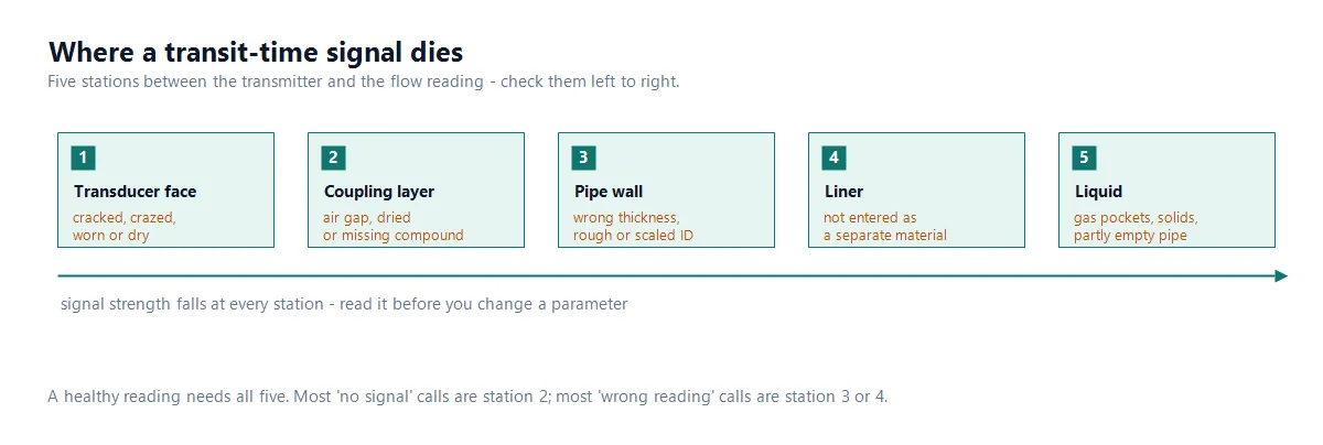
The acoustic path has five stations. A healthy reading needs all five; most "no signal" calls are station 2, most "wrong reading" calls are station 3 or 4.
1.1 The transducer face and the cable
Start where the acoustic path starts. A clamp-on face that is cracked, crazed or worn will not couple, whatever the menu says. Run a finger across it: it should be smooth with no erosion ring where the compound sits.
The manual is specific about cable: use the manufacturer's shielded signal cable, keep the run as short as possible, and never exceed 200 m between converter and transducer. A longer run, or a cable spliced with whatever was on the van, attenuates the receive signal below the 60 threshold and produces exactly the symptom you are chasing.
Check the connectors too. Loose terminals and oxidised pins are invisible from the display and common on outdoor installations. A multimeter across each core, with the far end shorted, settles it in thirty seconds.
1.2 Verify the five setup values against the pipe you actually have
M10 to M15 must describe the real pipe, not the one on the drawing:
Two errors recur. First, nominal wall thickness entered instead of measured: a DN200 pipe ordered as SCH 40 is 8.18 mm nominal, and the installed wall is rarely that. Measure with an ultrasonic thickness gauge at the transducer location, not at the flange. Second, a lined pipe entered as bare steel: a carbon steel pipe with an internal rubber or epoxy lining is two materials, and leaving the liner out computes a path through a wall that is not there.
After any change, re-read M91. If the ratio moves toward 100 %, you corrected something real. If it moves away, put it back.
1.3 Straight run, spacing and orientation
The straight-run requirement exists because the meter needs a developed velocity profile. Our service documentation uses at least 10 pipe diameters upstream and 5 downstream as the working minimum, and more after double bends in different planes or a partly closed valve.
On V-method clamp-on sets the transducers sit on the same generatrix, offset by half the spacing so the path crosses the centreline. That offset is the part installers skip.
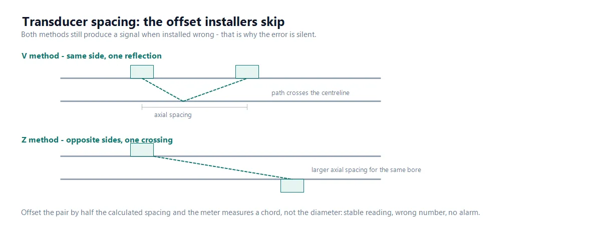
The offset is half the axial spacing on a V-method pair. Install at the wrong offset and the meter still finds a signal — it measures a chord instead of the diameter. The meter still finds a signal at the wrong offset — it just measures a chord instead of the diameter, which is why this fault produces a stable, wrong reading rather than an alarm.
Avoid the top of a horizontal pipe, where air collects, and avoid vertical downflow, where the pipe may run partly empty.
1.4 Full pipe, and how much gas is too much
Air is the most common cause of a signal that comes and goes. A transit-time meter needs a continuous liquid path; a gas pocket at the transducer scatters the pulse and the strength collapses below 60.
Look for physical evidence rather than the alarm: a high point in the run, a pump suction drawing air, a dosing point releasing dissolved gas, or a line that drains when the pump stops. Fit an air release valve at the high point, and if the layout is the cause, move the measurement point.
This failure is graded, not binary. A few fine bubbles do not stop a transit-time meter. They cost accuracy first — a drift of a few per cent with the display looking healthy — and only larger or intermittent quantities push strength under 60. If the reading is unstable rather than absent, suspect entrained gas before the electronics.
1.5 Interference, and what "marginal" looks like
Transducers work with microvolt receive signals, so they are more exposed than a pulse-output meter. Keep the signal cable away from VFD output cables, run it in its own conduit where possible, and ground the shield at one end only — both ends creates a loop that couples noise in rather than out.
If the fault appears only when a particular motor runs, you have found it. Move the cable, not a parameter. A strength that sits between 60 and 75 is the signature of a marginal installation: it works today and will not work after a season of rain and thermal cycling.
1.6 Single-path and multi-path sets fail differently
A single-path clamp-on set behaves like a switch: strength falls below 60 and the reading goes to zero. A multi-path set — the two-channel transducers in this range, or a four-channel converter — averages the paths, so one degraded path can be averaged away while the meter keeps reading. The symptom is not an alarm but a quiet under-read of a few per cent, which is worse, because nothing prompts anyone to look.
Read each path's strength and quality separately in M90 rather than the aggregate. If one path sits markedly lower than the others, that transducer is failing or that path is crossing a gas pocket; the absolute gap matters less than the fact that the paths disagree.
Fix 2 — RS485 Communication Failure
2.1 Physical layer before protocol
Reversed A and B is the most common RS485 fault and the most confusing symptom: perfect silence, no error, no partial frame. The terminals are marked 485+ and 485−; if the meter has never communicated since commissioning, swap the pair before anything else.
Then confirm the supply. The interface is isolated and the converter runs from DC 8–36 V (DC 24 V on the fix-mount). Long runs and undersized cable drop the voltage at the far end, and the meter resets intermittently rather than failing cleanly. Measure at the meter terminals with the loop connected, not open-circuit.
2.2 Termination and topology
RS485 is a bus, not a star. 120 Ω at both physical ends, and only at the ends — terminating every node loads the bus, and omitting the far end produces reflections that appear as CRC errors under load. Daisy-chain the nodes; spurs longer than a metre or two cause trouble.
2.3 The protocol setting that catches everyone
This is the fault that survives every correct baud rate, parity and address setting: the converter ships with MODBUS ASCII by default, and MODBUS-RTU is only active when "MODBUS-RTU Only" is selected in M52. A PLC configured for RTU will time out against a meter answering in ASCII, and nothing in the wiring or the serial parameters reveals it.
The instrument also supports M-BUS, FUJI expansion protocol and several domestic protocols, so M52 is worth reading before you touch M50 or M51.
Layer | What must match | Where |
Serial | Baud, data bits, stop bits, parity | M51 |
Protocol | ASCII vs RTU | M52 |
Addressing | Unique slave address on the bus | M50 |
2.4 Isolate the meter from the master
If wiring and parameters are right and there is still no reply, test each end. A USB-to-RS485 adapter at the meter terminals answers the question in one step: a reply there means the fault is in the run or the master; no reply means the meter or its address.
On the master side, a PLC communication module can fail while the PLC itself runs normally. Swap the module or test the port with another device before condemning the meter.
Fix 3 — Phantom Flow: a Reading When the Fluid Is Standing Still
A non-zero reading on a shut line is not a measurement error in the usual sense. The meter reports what it sees, and it is seeing movement. Three causes cover almost every case, and M92 tells you which.
3.1 Vibration from pumps, compressors and neighbouring equipment
Pipe vibration at a few hundred hertz modulates transit time and reads as velocity. The tell is that the reading appears when a specific machine runs, including machines on a different line sharing the same rack. M92 shows a large offset with no flow.
Fix it at the source: move the measurement point away from the pump discharge and from reciprocating equipment, and where relocation is impossible, break the vibration path with flexible connections or resilient supports.
3.2 Bubbles moving through a static column
Gas bubbles rise. In a static pipe that rising and drifting is real movement, and a transit-time meter cannot tell liquid moving from bubbles moving through liquid. Vent the high point, then find out why gas keeps appearing — a leaking seal, a suction line drawing air, or a process releasing dissolved gas.
3.3 Zero point and low-flow cut-off
The zero must be captured with the pipe full, the liquid static and no vibration. Use M32 to set it, and do not touch the pipe while it runs. A zero captured at commissioning with a pump running becomes a permanent offset that shows up as phantom flow at low rates.
Then set M31, the low-flow cut-off: below this velocity the meter treats flow as zero. The manual's working value is 0.03 m/s. Set it above the noise floor of a static line and below the lowest real flow you need to measure — once real flow exceeds the cut-off, the setting has no effect on the measurement.
3.4 The negative reading that is not a fault
If the display shows negative instantaneous flow while the process runs forward, the upstream and downstream probes are swapped. Swap and reinstall them. On insertion types the direction arrows on the two junction boxes must point in opposite directions and parallel to the pipe axis; on clamp-on sets the UP probe is upstream and the DN probe downstream.
Fix 4 — The Reading Drifts Over Weeks or Months
Slow drift is the expensive failure because nothing alarms. Four causes account for most of it.
Coupling degradation. The compound between transducer and pipe dries, hardens or is squeezed out. Strength falls gradually, the meter holds accuracy as long as it can, then the reading shifts. Re-couple on a schedule rather than after the reading is already wrong.
Fouling on wetted parts. Insertion and inline bodies collect scale, biofilm and process solids. A coated insertion probe still works until the deposit attenuates the pulse. On dirty duties, plan cleaning.
Temperature and sound velocity. The speed of sound in water rises by roughly 2–3 m/s per °C. A clamp-on installation commissioned cold and read hot carries a small error unless the fluid temperature in the parameters matches the running condition. M93 is the cross-check: compare the displayed sound velocity against the expected value for your liquid at its actual temperature. A figure off by more than a few per cent usually means the wrong fluid setting, not a failing transducer.
Profile factor at low velocity. Transit-time meters convert an average path velocity into a cross-sectional average with a profile correction factor, which assumes a developed turbulent profile. In a large pipe at low flow the profile may be laminar or transitional, the assumed factor no longer matches the flow, and the meter under-reads. If the duty runs at the bottom of the range, this is a sizing problem — the fix is a smaller bore, not a setting.
A warning about M35. The instrument factor is the ratio of actual to measured flow, and it must be entered from real calibration data. Using it to "correct" a drift caused by a dried coupling hides the fault and moves the error somewhere else.
Fix 5 — Repair or Replace the Transducer
Condition | Field repair | Replace |
Coupling dried or contaminated | Re-couple, re-read M90 | No |
Face scratched or lightly worn | Clean, re-couple, verify strength | If strength stays below 75 |
Face cracked, crazed or chipped | Not repairable | Yes |
Cable damaged within 1 m of the transducer | Not repairable | Yes |
Cable damaged in an accessible run | Splice in a junction box, re-verify | If strength degrades |
Connector corroded | Clean or replace the connector | If pins are eaten |
Strength fine, output dead | Check M62–M64 and the output wiring | Converter if confirmed |
The decision rule is strength after re-coupling on a known-good pipe. If a clean face and fresh compound restore 80+, the transducer is fine. If it stays at half of what a comparable pipe produces, the crystal or the face is gone and no amount of compound will bring it back.
The Handheld Unit Is the Cheapest Diagnostic You Own
The most common argument in a flow meter fault is whether the meter is wrong or the process is. A handheld clamp-on settles it in ten minutes without breaking into the line.
Measure the same pipe, at the same point, with the handheld while the fixed meter runs. If both agree, the measurement is right and the process has changed — a valve, a pump trim, a fouled line. If they disagree, the fixed meter's installation or pipe data is wrong, and M90 and M91 on the fixed unit will show which.
The handheld is also the fastest way to confirm a repair: re-couple the fixed transducer, then compare against the handheld rather than against yesterday's number.
Why This Range Produces Fewer of These Faults
Every fault above maps to a design decision. This is not a claim that the meter cannot fail — it is a list of which failures were designed out, and where to look if one appears anyway.
Design choice | Fault it removes | Section |
Two-path transducers (M1-2, ATC-1-2) | A single degraded path averaged into a healthy-looking reading | 1.6 |
Shielded signal cable, 200 m limit stated | Signal loss from improvised cable runs | 1.1 |
HT variants rated to 160 °C | Coupling cook-through on hot lines | 1.1 |
IP68 fix-mount, potted terminals | Water ingress in pits, sumps and washdown | 1.1 |
ASCII / RTU switchable in M52 | The silent protocol mismatch | 2.3 |
Handheld in the same range | The meter-versus-process argument | Handheld section |
Preventive Maintenance
Inspect and re-couple clamp-on transducers every 12 months, every 6 months outdoors or on high-vibration lines.
Log M90 strength and quality at each visit. A falling trend predicts a failure months before the reading moves.
Re-measure wall thickness on old, lined or corroded pipe — the value entered at commissioning does not stay true.
Re-check the zero (M32) after any work on the line, any pump change and any change of fluid.
Inspect insertion and inline bodies on duties with solids or scaling.
Verify the RS485 segment after any change to the bus; a new node is the usual cause of a bus that worked for two years.
What to Send Us When You Escalate
Remote diagnosis is fast with complete data and slow without it. Send:
Model and serial number of converter and transducer set.
Pipe outside diameter, measured wall thickness, material and liner.
Liquid, normal and minimum flow, temperature and pressure.
Photos of the installation, 2 m upstream and downstream included.
M90 strength and quality, M91 ratio, M93 sound velocity, with the pump running and stopped.
For communication faults: a screenshot of M50–M52 and the serial settings on the master.
With those six items most faults that reach us are resolved without a site visit.
FAQ
Why does my ultrasonic flow meter show a signal but no flow reading? A signal above 60 with no flow usually means the meter is timing a path that does not match the pipe, or the flow is below the low-flow cut-off. Check M91 first: outside 97–103 % the pipe data or spacing is wrong. Then check M31, the low-flow cut-off, before suspecting the transducer.
What signal strength do I need for the meter to work? 60.0 or above on the M90 scale of 00.0–99.9. Between 60 and 75 the meter runs but the installation is marginal; 75–80 is good and above 80 is excellent. Below 60 the meter cannot measure, regardless of settings.
Can an ultrasonic flow meter measure a pipe that is not full? Not reliably. Transit-time measurement needs a continuous liquid path between the transducers; a partly filled pipe produces fluctuating signal and unpredictable readings. Relocate the measurement point to a section that stays full, or choose a technology that tolerates it.
Will a few bubbles really stop the measurement? No. A few fine bubbles cost accuracy first — a drift of a few per cent with the display still healthy — and only larger or intermittent quantities push signal strength under 60. A meter that stops entirely is seeing a gas pocket or a dry section, not fine entrained air.
Why does the reading appear only when the pump runs with the valve closed? Vibration. A closed valve with a running pump puts mechanical vibration into the pipe, and the resulting transit-time difference reads as velocity. Isolate the pump to confirm, then move the transducers away from the vibration source or break the vibration path.
Why can't my PLC read the meter over RS485 when the baud rate and address are correct? Check M52. The converter ships with MODBUS ASCII by default, and MODBUS-RTU requires selecting "MODBUS-RTU Only". A master configured for RTU will time out against a meter answering in ASCII even with every serial parameter matching.
Do I need to terminate both ends of the RS485 bus? Yes — 120 Ω at each physical end and only at the ends. Terminating intermediate nodes or omitting the far-end resistor both cause reflections that appear as intermittent CRC errors rather than a clean failure.
How often should clamp-on transducers be re-coupled? Every 12 months as a baseline, every 6 months outdoors or on high-vibration lines. The compound dries and strength falls gradually, so the interval should follow the M90 trend rather than wait for the reading to drift.
References and Further Reading
ISO 12242, Measurement of fluid flow in closed conduits — Ultrasonic transit-time meters for liquid.
The site's ultrasonic flow meter guide covers selection and principle.
If the liquid is conductive, an electromagnetic flow meter removes much of this failure class by having no acoustic path at all.
Product range: ultrasonic flow meters — clamp-on, insertion and inline bodies, split and fix-mount converters, handheld units for spot checks.
If you are commissioning a JUJEA clamp-on, insertion or inline set and the numbers do not behave, send the six items above to our after-sales team and we will work the fault from M90 and M91 rather than from a list of settings.
Next Step
Ethan Liu
Ethan Liu is JUJEA's technical content specialist, translating complex sensor integration and industrial automation concepts into practical insights for engineers, system integrators, procurement professionals, and decision-makers worldwide.


 한국어
 français
 Deutsch
 Español
 italiano
 русский
 português
 العربية
 tiếng việt
 čeština