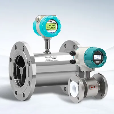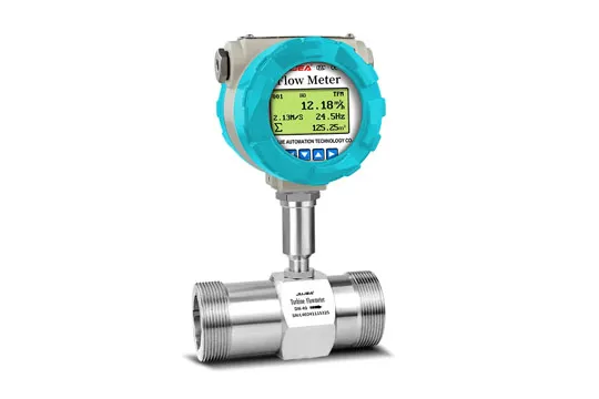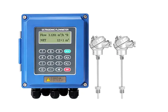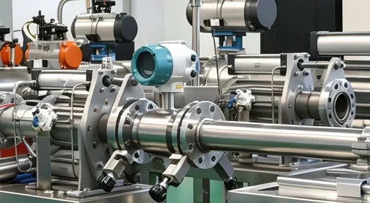
An electromagnetic flowmeter that shows no flow, reads inaccurately or throws an alarm code is usually reporting a fixable condition — a wiring fault, a coated electrode, a parameter mismatch or a grounding problem — not a dead instrument. This guide maps the four alarm codes you will actually see (FQH, FQL, FGP, SYS) to their causes, then walks through the four highest-frequency complaints in order: no flow display, empty-pipe alarm, RS485 communication failure, and unstable or inaccurate readings. Every diagnostic step below is the same sequence our service engineers use in the field. Confirmed faults that cannot be repaired in situ — corroded electrodes, water ingress, damaged liners — end in a sensor replacement, and the final section tells you how to avoid the second failure.
Quick definition: an electromagnetic (mag) flowmeter measures the voltage induced in a conductive liquid as it moves through a magnetic field, per Faraday's law; there are no moving parts, so most failures originate in the signal path — electrodes, cables, excitation coil, grounding and converter settings — rather than in the flow tube itself.
Alarm Code Reference Table (FQH, FQL, FGP, SYS)
Start here. These four codes cover the overwhelming majority of field alarms on this instrument family. Codes are displayed on the converter and are model-specific — always confirm the meaning against the manual supplied with your meter. They are also commonly searched as flow meter error codes, so the table below lists each code with its plain-language meaning.
Code | Alarm | What it actually means | First action |
FQH | High-flow (upper-limit) alarm | Measured flow has exceeded the upper warning setpoint configured in the parameters | Compare the actual process flow against the setpoint; re-range the warning if it was mis-set rather than chasing a meter fault |
FQL | Low-flow (lower-limit) alarm | Flow has fallen below the lower warning setpoint | Confirm genuine low flow, then check for a partially closed valve, air in the line, or solids bridging the tube; verify the setpoint |
FGP | Empty-pipe alarm | The meter is not detecting a valid flow signal — the electrodes are effectively dry or the medium is out of range | Check signal-wire terminals, medium conductivity (see below) and the empty-pipe alarm threshold setting |
SYS | Excitation alarm | The excitation coil circuit is abnormal — open coil, shorted or non-insulated winding | Power-cycle to clear a transient/software lock-up, then measure the excitation coil resistance; escalate if it is out of specification |
Engineering note: FQH and FQL are process alarms driven by your own setpoints — they usually indicate the alarm is configured tighter than the process actually runs. FGP and SYS are instrument alarms and require physical diagnosis.
Fix 1 — Flow meter Shows No Flow Display
Work through these three checks in order. Each one eliminates a layer of the signal chain — the same logic applies to any electromagnetic flow meter — so you never replace a sensor for a blown fuse.
Step 1: Verify the power supply
Measure the supply voltage at the meter with a multimeter and confirm it sits inside the instrument's rated range (this family runs on 100–240 VAC, 50/60 Hz). If the voltage is abnormal, inspect the power wiring, the socket/terminal block and the fuse, then repair or replace the faulty component before investigating anything else. Unstable supply is a common cause of a display that appears and disappears.
Step 2: Check the signal and excitation cabling
Inspect the cable between sensor and converter — on split-type meters this is where most faults live. Verify that each conductor is correctly landed and firmly tightened, with no loose or disconnected wires. Use the multimeter's continuity function to test each core: an open circuit or a short between cores means replacing the signal cable. Poor shielding continuity to earth produces exactly the same "no display" symptom as an open core.
Step 3: Inspect electrodes and the sensor
Isolate and dismantle the sensor, then inspect the electrode surfaces for deposits, scaling or foreign matter. Clean them with a soft brush and a suitable cleaning agent, then rinse with clean water and refit. If an electrode is severely corroded, or the liner is cracked, blistered or torn, the sensor has reached end of life — cleaning will not recover it, and a replacement sensor is the correct fix.
Symptom | Most likely check | Corrective action |
Display dead, no backlight | Supply voltage, fuse, terminal tightness | Restore stable supply; replace fuse/terminal as needed |
Display on, zero flow shown | Signal cable continuity; shielding | Re-land or replace signal cable; restore shield ground |
Flow shown but drops to zero intermittently | Loose electrode or excitation connection | Tighten terminals; inspect electrode seating |
Electrodes heavily fouled or corroded | Electrode surface, liner condition | Clean; if corrosion/liner damage is severe, replace the sensor |
Fix 2 — FGP Empty-Pipe Alarm
The FGP alarm on an electromagnetic flow meter means the converter is not seeing a valid flow signal, which it interprets as an empty (unwetted) tube. Four causes account for nearly all occurrences:
Signal wiring problems.
1. Check whether the electrode signal wires are loose, making intermittent contact, or landed on the wrong terminals. Re-terminate and tighten. A wiring error is the single most common cause of a spurious FGP.
Conductivity below the measurable range.
2. The theoretical lower limit is about
5 µS/cm, but the practical requirement is much higher — plan for at least 30 µS/cm measured online — because dissolved gases can inflate an offline reading that vanishes once the liquid is in the pipe. If your medium is borderline, validate conductivity online, not from a lab sample.
Empty-pipe alarm threshold mis-set.
3. The threshold is a configurable parameter; if it was set too high for a low-conductivity medium, the meter will alarm on a genuinely full pipe. Re-check the setting against the process data.
Genuinely empty or partially filled pipe.
4. Air pockets, a drained line, or mounting at the highest point of the system all de-wet the electrodes. Correct the hydraulic conditions rather than the meter.
Fix 3 — RS485 Communication Failure
RS485 faults on an electromagnetic flow meter split cleanly into three layers. Diagnose in this order — hardware first, then parameters, then the devices themselves.
Layer 1 — Hardware and wiring
● Test the 485 pair for open circuits, short circuits and physical damage with a multimeter; replace the communication cable if faulty.
● Inspect the connectors: loose, oxidised or damaged terminals must be cleaned or replaced. Oxidation on outdoor installations is a frequent and easily missed cause.
Layer 2 — Communication parameters
Every device on the bus must use identical serial settings. If any single parameter differs, communication fails silently.
Parameter | Requirement | Notes |
Station address / polling address | Must be unique per device | Duplicate addresses collide; change one via the setting menu |
Baud rate | Identical across all devices | Mismatch = framing errors or no response |
Data bits | Identical | — |
Stop bits | Identical | — |
Parity | Identical | Parity mismatch is a classic intermittent-fault source |
Protocol | Same protocol on the same bus | Mixed protocols require a converter/gateway |
Layer 3 — Device faults
● If cabling and parameters are correct, suspect the meter's 485 communication module: restart the flowmeter first (this clears transient states), and escalate to the factory if the port stays dead.
● Test the other end of the link. The host PC, PLC or data logger may have the faulty port or communication module — swap it for a known-good device to isolate which end is failing.
Fix 4 — Inaccurate Flow Reading or Unstable Output Signal
Six root causes explain almost all accuracy complaints. Check them in this sequence, cheapest and most likely first.
4.1 Installation position
Confirm the sensor sits on a straight run with the required upstream and downstream straight lengths (our installation data specify at least 5D upstream and 3D downstream), and that it is not installed close to bends, valves or pumps. Disturbed flow profiles produce errors that no amount of calibration can remove. Mount horizontally with the electrode axis horizontal; for solids-bearing media mount vertically with flow upward so the tube stays full.
4.2 Deposits and coating on the sensor bore
Impurities and particles in the medium gradually deposit on the sensor bore and electrodes. A coating changes the effective tube diameter and wall smoothness and insulates the electrode from the liquid — the meter under-reads or drifts while the process looks perfectly normal. Clean the sensor periodically. For heavy scaling, chemical cleaning is acceptable provided the cleaning agent is selected for the liner and electrode materials in the meter; an aggressive agent can destroy a PTFE liner or attack a Hastelloy electrode, converting a maintenance task into a sensor replacement.
4.3 Zero-point error
Zero calibration must be performed on a full pipe with no flow. Use the converter's zero-adjustment function and set the zero accurately. If zero drifts repeatedly, re-run the procedure — and if it will not hold, escalate for professional/factory calibration rather than compensating with an offset.
4.4 External electromagnetic interference
Interference from motors, transformers, variable-frequency drives and switching equipment couples into the electrode circuit and shows up as jitter or bias.
● Use shielded cable for the signal path and ground the shield reliably.
● Move the meter away from strong interference sources, or shield/isolate the source itself.
● Tighten the grounding conductors; if the installation is still noisy, re-build the earth electrode with suitable material and placement. On lined or non-conductive piping, grounding rings/electrodes must be installed — they are not optional.
4.5 Loosened internal parts
Check whether the electrodes, excitation coil and their connections have worked loose (vibration is the usual culprit). Re-tighten with the correct tools and confirm each part sits in its designed position.
4.6 Sensor damage
Chemical attack or water ingress into the sensor terminates the measurement. Minor mechanical damage — a chipped housing, a degraded seal — can be repaired with the correct spare parts. Damage that has reached the electrodes, liner or coil assembly is not field-repairable and requires sensor replacement.
Fix 5 — SYS Excitation Alarm
The SYS alarm points at the excitation circuit — the coils that generate the magnetic field. Two diagnostic steps resolve it:
Power-cycle the instrument.
1. A transient disturbance or a software lock-up is cleared by a clean restart. If the alarm does not return after restart, log the event and monitor.
Measure the excitation coil circuit.
2. Check the coil resistance on the sensor side and compare it against the value specified for your model. An open circuit, an abnormal reading, or a winding that fails insulation checks indicates a coil fault. Coil faults are not repaired in the field — contact the factory with the measurements.
Tip: record the measured resistance in your maintenance log. Trend data across visits makes the next diagnosis faster, and it gives the factory a firm basis for the repair decision.
Repair or Replace? Making the Call on a Damaged Sensor
Condition | Decision | Rationale |
Chipped housing, degraded seal, minor mechanical damage | Repair | Replace the damaged parts and restore sealing; measurement path unaffected |
Electrode corrosion, liner blistering or tearing, water ingress | Replace sensor | The measuring circuit is compromised; repair cannot restore accuracy |
Repeated corrosion/abrasion failures on the same medium | Replace with upgraded materials | Select the liner and electrode alloy against the actual medium — e.g. PTFE-family liners and Hastelloy electrodes for aggressive chemistry — instead of repeating the same specification |
When specifying a replacement electromagnetic flow meter, treat the failure as process data: the material that failed is telling you the chemistry, temperature or abrasiveness the meter actually sees, which is often more revealing than the original process data sheet.
Preventive Maintenance That Prevents These Alarms
Interval | Task | Purpose |
Monthly | Compare the reading against a second reference; review alarm history | Catch drift before it affects reporting or control |
Quarterly | Inspect and clean electrodes/bore during a planned shutdown; verify grounding and shield continuity | Prevent coating-induced drift and interference faults |
Annually | Verify calibration against a traceable reference; check seals and cable glands for water ingress | Maintain measurement confidence and IP integrity |
After any process change | Re-validate conductivity, temperature and materials | Process changes — not meter age — cause most repeat failures |
What to Send Us When You Escalate
To resolve a fault in one exchange rather than five, prepare: the model and serial number, the medium and its measured conductivity, the alarm code displayed, current parameter list (station address, baud rate, parity, setpoints), excitation coil resistance readings, installation photos, and the date of the last calibration. Our engineers respond within one hour on working days.
FAQ
Q: Why does my electromagnetic flowmeter show no flow when the pump is running?
A: Check in this order: supply voltage at the meter, fuse and terminals; then signal-cable continuity between sensor and converter; then electrode fouling and liner condition. A display that is on but shows zero usually points to the signal path or an empty/partially filled pipe, not to the sensor being dead.
Q: What does the FGP code mean on an electromagnetic flowmeter?
A: FGP is the empty-pipe alarm: the meter is not detecting a valid flow signal. The usual causes are loose or mis-wired electrode signal cables, medium conductivity below the measurable range (practically at least 30 µS/cm measured online), an empty-pipe alarm threshold set too high, or a genuinely empty/partially filled pipe.
Q: What does the SYS excitation alarm mean and can I fix it myself?
A: SYS indicates an excitation-coil circuit fault. Power-cycle the meter first to clear transient interference or a software lock-up; if the alarm persists, measure the excitation coil resistance and insulation and compare with your model's specification. Coil faults are not field-repairable — escalate to the factory with the readings.
Q: How do I fix RS485 communication on a flowmeter?
A: Work in three layers: (1) hardware — test the 485 pair for open/short/damage and clean oxidised connectors; (2) parameters — station address, baud rate, data bits, stop bits and parity must be identical on every device, with a unique address per meter and one protocol per bus; (3) devices — restart the meter, and swap-test the host/PLC port to identify which end is failing.
Q: Why is my flowmeter reading inaccurate even though it is new?
A: New meters are rarely out of calibration; inaccurate readings usually come from installation or the medium. Confirm straight-run distances (at least 5D upstream, 3D downstream) and avoid installing near bends, valves or pumps; check for coating on the bore and electrodes; verify zero calibration on a full, no-flow pipe; and eliminate electromagnetic interference with shielded, properly grounded cable.
Q: How should I clean a coated electromagnetic flowmeter sensor?
A: Isolate the line, remove the sensor and clean the bore and electrodes with a soft brush and a compatible cleaning agent, then rinse with clean water. For heavy scaling, chemical cleaning is acceptable only if the agent is selected for your liner and electrode materials — the wrong chemical can destroy a PTFE liner or corrode a Hastelloy electrode.
Q: Can a corroded or water-damaged sensor be repaired?
A: Minor mechanical damage (housing, seals) can be repaired with spare parts. Electrode corrosion, liner damage or water ingress compromise the measuring circuit and require sensor replacement — and if the same medium caused the failure, upgrade the liner and electrode materials to match the actual process chemistry.
Q: What information should I send the manufacturer for a fault diagnosis?
A: Model and serial number, medium and measured conductivity, the alarm code, the current parameter list (address, baud rate, parity, setpoints), excitation coil resistance readings, installation photos and the last calibration date. This typically allows a diagnosis in a single exchange.
References and Further Reading
ISO 20456:2017 — Measurement of fluid flow in closed conduits: guidance for the use of electromagnetic flowmeters for conductive liquids
● — the international reference for installation, operation and performance verification.
Official preview (ANSI webstore)
OMEGA Engineering, Flow Control technical reference
● — independent overview of flowmeter technologies and general selection/maintenance guidance, including why obstructionless meters such as mag meters fail mainly through coating and electronics.
omega.com — flow control reference
Endress+Hauser, Proline Promag H Technical Information (TI01578D)
● — manufacturer documentation on mag meter materials and grounding-ring/electrode compatibility.
Download TI01578D (PDF)
Fault codes are a starting point, not a verdict — and a meter that alarms twice for the same reason usually needs a material or installation change, not another reset. Our engineers support JUJEA electromagnetic flowmeters with free remote diagnosis, a one-hour response target and a 18-month warranty, backed by an in-house calibration laboratory and 72-hour burn-in testing on every unit (ISO 9001/14001/45001 and CE/ROHS/TUV/SGS-certified factory).
Send us your fault data · Browse JUJEA electromagnetic flowmeters
Electromagnetic flowmeter selection guide
Ethan Liu
Ethan Liu is JUJEA's technical content specialist, translating complex sensor integration and industrial automation concepts into practical insights for engineers, system integrators, procurement professionals, and decision-makers worldwide.


 한국어
한국어 français
 Deutsch
 Español
 italiano
 русский
 português
 العربية
 tiếng việt
 čeština