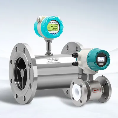
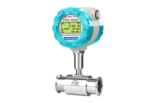
An electromagnetic (mag) flowmeter looks simple — a straight flanged tube, two electrodes, no moving parts. Yet most field problems trace back to decisions made before the meter was ordered: the wrong liner for the chemical, an electrode alloy that the medium attacks, a line size that keeps velocity below 0.3 m/s, or a grounding loop nobody designed. This guide walks through the full selection sequence — process data, sizing, liner, electrode, pressure/temperature rating, converter outputs, grounding and installation — and gives you a checklist you can hand to any supplier. We use our own JUJEA integrated meters (DN4–DN1200) as a concrete example, but the selection logic applies to any manufacturer's instrument.
How an Electromagnetic Flow meter Works — and When to Use One
A magnetic flowmeter measures flow using Faraday's law of electromagnetic induction. Two excitation coils outside the measuring tube generate a magnetic field perpendicular to the flow direction; as a conductive liquid moves through that field, an electromotive force proportional to the flow velocity is induced between a pair of electrodes mounted flush in the tube wall:
E=KxBxVxD
where E is the induced voltage, K the instrument factor, B the magnetic induction intensity, V the average flow velocity and D the tube inner diameter. Because the signal is linear with velocity and there is no obstruction in the flow path, a mag meter offers a wide turndown, negligible pressure loss and equal accuracy in forward and reverse flow — the liquid itself is the only moving part.
That geometry defines the application envelope:
A mag meter is a strong fit when… | A mag meter is the wrong tool when… |
The liquid is electrically conductive | The fluid is a gas, steam or vapor |
The medium is corrosive or abrasive | The liquid is non-conductive (hydrocarbons, most oils, solvents) |
The process needs no pressure drop | Conductivity is below ~5 µS/cm theoretical (below ~30 µS/cm in practice — see below) |
Slurries or liquid–solid two-phase flow | The pipe runs partially full or the electrode is never wetted |
Bidirectional or pulsating flow must be measured accurately | Hygienic approvals beyond standard food-grade materials are required |
The conductivity limit deserves precision because it is widely misquoted. Theoretically an electromagnetic flowmeter can measure media above 5 µS/cm, but the practical recommendation is to operate well above that — at least 30 µS/cm measured online — because dissolved carbon dioxide or nitrogen can raise an offline reading that disappears once the liquid is in the line. If your medium is borderline, validate with an online conductivity measurement, not a lab sample.
When in doubt about whether a mag meter fits your process, the questions a supplier needs answered are exactly the ones in the next section. Spend ten minutes filling them in and you will eliminate most mis-selection.
Step 1 — Write Down the Process Data Before You Look at Meters
Selection starts on paper, not in a catalog. Collect, at minimum:
Medium identity and composition
including trace components. A "dilute acid" stream can contain 200 ppm chlorides that rule out 316L electrodes.
Conductivity(online value, µS/cm)
Density,viscosity,solids content and particle size.
Flow envelope
normal, minimum and maximum flow rate (or velocity), plus expected turndown. Batch plants often run a meter at 10% of design flow between batches; that changes both sizing and the need for low-flow correction.
Process temperature and pressure
Piping geometry
available straight runs upstream/downstream, orientation options, vibration, and whether the process can be shut down for maintenance.
Signal requirements
local display only, 4–20 mA, pulse totalization, RS485/Modbus, HART, or wireless/Bluetooth configuration.
Site conditions
outdoor exposure, flooding/submersion risk, ambient temperature range, hazardous area classification.
Step 2 — Size the Meter: Velocity Is the Master Variable
A mag meter measures velocity; the flow rate is calculated from velocity and the tube cross-section. The sizing objective is to keep the operating velocity in the accurate, stable region of the meter's range — as a practical rule between roughly 0.5 and 5 m/s, with 0.3 m/s as the practical low end for stable measurement on most full-bore meters.
The conversion between flow rate and velocity for a full pipe is:

The table below shows actual values from our GTIMEASURE pipeline meter data (maximum measurable velocity is set at 12 m/s by default on this family, configurable between 1 and 24):
DN (mm) | Min flow @ 0.3 m/s (m³/h) | Common flow @ 1 m/s (m³/h) | Max flow @ 7 m/s (m³/h) |
DN25 | 0.53 | 1.77 | 12.39 |
DN50 | 2.12 | 7.07 | 49.48 |
DN80 | 5.43 | 18.10 | 126.67 |
DN100 | 8.48 | 28.27 | 197.92 |
DN150 | 19.09 | 63.62 | 445.32 |
DN200 | 33.93 | 113.10 | 791.70 |
DN300 | 76.34 | 254.47 | 1781.29 |
DN500 | 212.06 | 706.86 | 4948.02 |
Three sizing mistakes dominate:
Oversizing.
A DN300 meter on a line that normally flows 80 m³/h runs at ~0.3 m/s, where noise and zero drift become a meaningful fraction of the signal. Prefer a smaller meter over a turndown gamble.
Ignoring low-flow behavior.
Below ~0.5 m/s, many meters benefit from a piecewise flow-correction function that re-linearizes the velocity curve at low flow points. Our converter implements a four-point correction (each segment applies a coefficient to the original velocity) that restores linearity without re-calibration — worth asking your supplier about if your turndown is steep.
Sizing to the pipe, not the flow.
Standard practice is to size so the meter can be flanged into the line with reducers when the flow demands a smaller bore — but only after checking that the resulting velocity stays in range and that upstream/downstream straight runs remain adequate.
Step 3 — Choose the Liner: Corrosion, Temperature and Abrasion
The liner is the meter's corrosion barrier and the single most consequential material decision. It isolates the metal tube and flange faces from the medium and, for insulating liners, prevents the induced signal from shorting through the tube wall. Liner choice is driven by chemistry, temperature and abrasion, in that order.
Liner material | Typical strengths | Watch out for | Typical service |
Chloroprene rubber (CR / Neoprene) | Low cost, good abrasion resistance, handles dilute acids and alkalis | Not for strong oxidizers, oils or high temperature | Water, wastewater, slurries, raw sewage |
Fluorosilicone rubber (FVMQ) | Broad chemical resistance in a flexible liner, higher temperature than CR | Cost; compatibility must be verified per chemical | Mid-temperature chemical and industrial streams |
PTFE (F4) | Excellent corrosion resistance, low friction, non-stick | Limited temperature/pressure retention in larger sizes; lower abrasion tolerance than rubber | Strong acids and alkalis, general chemicals |
FEP (F46) | Chemically similar to PTFE, pinhole-free, better for vacuum service | Cost | Vacuum-prone chemical lines, aggressive media |
PFA | Highest performance fluoropolymer liner: best temperature rating, excellent chemical resistance, smooth for hygienic service | Highest cost of the group | Hot concentrated chemicals, food and pharmaceutical process lines |
On our pipeline meters the medium temperature rating ranges from –20 °C up to +180 °C depending on liner and version (rubber-family liners sit at the lower end, fluoropolymers at the upper end); plug-in sensors are rated –25 to +120 °C. Do not assume a liner rated for a chemical at 20 °C survives the same chemical at 90 °C — concentration and temperature act together, and liner data sheets (or your supplier's compatibility charts) must be checked at the actual process conditions, including CIP peaks.
Two practical notes: for abrasive slurries, a rubber liner wears more evenly than a fluoropolymer and vertical mounting distributes wear uniformly; and liner selection must never be confused with electrode selection — they face different attack modes.
Step 4 — Choose the Electrodes: Match the Alloy to the Chemistry
A pair of measuring electrodes contacts the medium directly, so electrode material is chosen for resistance to the specific chemical, not for conductivity. Most suppliers offer the same core set; JUJEA offers 316L stainless steel, Hastelloy C, Hastelloy B, titanium, tantalum and platinum.
Electrode material | Typical application guidance |
316L stainless steel | Clean and municipal water, wastewater, many neutral and mildly aggressive media — the default, and the most economical |
Hastelloy C | Oxidizing acids, chloride-laden media, seawater-adjacent chemistries — very broad general-purpose choice for aggressive service |
Hastelloy B | Reducing environments, hydrochloric acid at moderate concentrations |
Titanium | Seawater, chlorides, hypochlorite, brine — excellent pitting resistance |
Tantalum | Hot strong acids, including hydrochloric and sulfuric acid; behaves almost like glass in corrosion resistance |
Platinum | The most corrosion-resistant option for the most demanding chemistries |
Two selection traps to avoid:
Do not validate an electrode alloy from memory.
Compatibility depends on exact concentration, temperature and trace contaminants. Send the full composition to the supplier and let engineering cross-check it.
Do not forget grounding electrodes or grounding rings.
Mag signals are tiny (millivolt-level), and a meter without a proper electrical reference drifts with process potentials. Grounding electrodes (and grounding rings for lined or non-conductive pipes) tie the liquid to the instrument ground; verify that any grounding ring material is compatible with the electrode material — a mismatch can create a galvanic corrosion cell, a point emphasized in Endress+Hauser's Promag technical documentation (see References).
Step 5 — Check Pressure, Temperature and Protection Ratings
With materials settled, confirm the mechanical envelope. Our pipeline meters are flanged (GB/T 9119-2000 carbon steel as standard, stainless steel optional; DIN, ANSI and JIS flanges available on request) with the following pressure steps: DN15–DN50 ≤ PN4.0 MPa; DN65–DN150 ≤ PN1.6 MPa; DN200–DN600 ≤ PN1.0 MPa; DN700–DN1200 ≤ PN0.6 MPa (higher ratings custom-engineered).
Protection class is an installation decision as much as a spec: IP65 suits indoor and sheltered outdoor mounting; IP68 allows submersion — on our split-type IP68 sensors the sensor can be immersed up to 3 m or buried up to 5 m, which is why you see mag meters inside flooded valve pits in municipal service. If the meter goes outdoors, under a pit cover or anywhere it can be washed down, do not economize on the IP rating. Ambient limits are typically –10 to +55 °C operating and –40 to +65 °C storage, so a black flow tube in a Middle East sun or a Siberian winter needs either shelter or a spec check.
Step 6 — Select the Converter: Outputs, Protocols and Diagnostics
The converter turns the microvolt electrode signal into something your control system can use. Standard analog outputs on this class of meter are 4–20 mA (≤ 750 Ω load) for flow rate and pulse/frequency output (up to 5000 Hz, pulse weight settable from 0.001 L to 1 m³) for totalization, plus a status/alarm output. Digital options include RS485 serial (Modbus RTU), HART and Bluetooth 4.0 for configuration via a phone app — useful when the meter sits in a pit or on a tank farm where opening the cover is inconvenient.
Two converter features matter more than the LCD (ours is a 128×64 graphic display, LCD with white backlight or OLED, in English and Chinese):
Self-diagnostics
including electrode-contamination detection that flags coating build-up on the electrode before the reading drifts. Coating is the classic failure mode of mag meters in wastewater and pulp service: an insulating deposit progressively insulates the electrode and the meter reads low while the process looks normal.
Low-flow correction
the four-point linearization described in Step 2, which keeps small-flow accuracy without sending the meter back for re-calibration.
Power supply is normally 100–240 VAC (50/60 Hz, ≤ 15 VA) on line-powered converters — check your site supply before ordering.
Step 7 — Grounding and Installation: Where Accuracy Is Won or Lost
A mag meter that is perfectly specified but badly installed will not meet its accuracy class. The non-negotiables, drawn from our installation manual and consistent with ISO 20456:2017 guidance:
Straight run:
at least 5 pipe diameters upstream and 3 diameters downstream of the sensor (no valves, reducers or elbows inside that zone). Valves upstream of the meter depressurize the liquid and can release dissolved gas — which is why the same manual that demands 5D/3D also instructs installing the meter upstream of the valve wherever possible.
Orientation:
mounted horizontally, keep the electrode axis horizontal
(not at the top or bottom) so rising bubbles cannot collect on an electrode and sediment cannot bury it. For solids-bearing or slurry media, mount vertically with flow upward,so the tube always stays full and wear is even never.
install on the pump suction side (vacuum can collapse the liner and de-wet the tube), never at the highest point of a line (air accumulates and the meter over-reads or under-reads unpredictably), and keep back pressure downstream of the sensor.
where a pipe drops more than ~5 m, install air-release valves downstream of the meter.
if the line cannot be shut down, install a bypass with isolation valves so the meter can be removed, cleaned or verified without stopping production.
keep the sensor away from motors, transformers and variable-frequency drives, and do not share power feeds with heavy switching loads.
support the meter so the pipe does not transmit strain; when new piping has just been welded, flush the line before installation — welding slag destroys a PTFE liner in minutes. Alignment tolerance on flanged mounting is typically ≤1.5 mm (DN < 50), ≤2 mm (DN65–300) and ≤4 mm (DN ≥ 350).
connect the sensor housing, grounding electrodes/rings and converter to a common earth. On lined or plastic piping the liquid is electrically isolated, so grounding rings become mandatory, not optional.
Verification, Calibration and Maintenance Realities
Accuracy on a spec sheet is meaningless without a traceable calibration behind it. When you evaluate a supplier, ask three questions:
Is there a real calibration rig?
We calibrate every meter individually on an in-house liquid-flow calibration stand (weighing-method, traceable to national standards) and ship each unit with its own calibration data — not a "representative" certificate copied for the batch.
What is the burn-in and QC regime?
Ours includes 72-hour aging under temperature extremes and EMI before release, with a unique serial number tracing production → calibration → shipment → any later service event. It is the difference between a factory that meters and a factory that assembles.
What happens after installation?
Periodic checks: empty the line and verify zero, inspect the electrodes for insulating coating (and clean if needed), and re-verify against a reference or the calibration rig on a schedule scaled to how critical the measurement is. ISO 20456:2017 gives structured guidance on installation, operation and performance verification for conductive-liquid flow measurement; keep a copy in your instrument file.
A Working Selection Matrix for Common Applications
Application | Typical liner | Typical electrode | Mounting / notes |
Municipal wastewater, raw sewage | CR rubber | 316L / Hastelloy C | IP68 if in pits; bypass for cleaning; watch grease and rags, not chemicals |
Chemical dosing, acids & alkalis | PTFE / FEP / PFA | Hastelloy C / Ta / Pt | Grounding rings mandatory on plastic pipe; validate alloy vs full composition |
Food & beverage, CIP lines | PFA | 316L | Smooth bore, no dead legs; confirm liner temperature vs CIP peaks |
Abrasive slurry, mining tailings | CR rubber (wear) | 316L / Hastelloy C | Vertical, flow upward; expect liner as a wear part; low velocity design |
Pulp stock | Rubber / FEP | 316L / Hastelloy C | Vertical preferred; electrode fouling monitoring useful |
Potable water networks | CR / PTFE | 316L | Accuracy class matters for balancing; telemetry via RS485/Modbus |
Seawater, brine, desalination | Rubber / PTFE | Titanium | Chloride pitting drives electrode choice |
Large conduits, irrigation mains | — (plug-in sensor DN80–DN3000) | 316L / Hastelloy C | Plug-in (1.5% accuracy) for hot-tap large lines where full-bore cost is unjustified |
Every row above is a starting point, not a conclusion — final material selection must be validated against the actual process chemistry, temperature and cleaning regime.
References and Further Reading
ISO 20456:2017 — Measurement of fluid flow in closed conduits: guidance for the use of electromagnetic flowmeters for conductive liquids.
The international reference standard for selection, installation and performance verification of mag meters.
Read the official preview (ANSI webstore)
OMEGA Engineering, Flow Control technical reference.
Independent overview of flowmeter families — including why electromagnetic meters suit conductive liquids and slurries with no pressure drop — plus general selection and maintenance guidance.
omega.com — flow control reference
Endress+Hauser, Proline Promag H Technical Information (TI01578D).
Manufacturer documentation on mag meter material selection — including the requirement that grounding-ring material be compatible with electrode material to avoid galvanic corrosion.
Download TI01578D (PDF)
FAQ
Q: What liquids can an electromagnetic flowmeter measure?
A: Electrically conductive liquids and liquid–solid mixtures: water, wastewater, acids, alkalis, slurries, pulp stock, brine and most aqueous process streams. Theory starts at roughly 5 µS/cm, but plan for at least 30 µS/cm measured online for reliable operation. Gases, steam and non-conductive liquids such as hydrocarbons cannot be measured.
Q: What is the accuracy of an electromagnetic flowmeter?
A: A full-bore (pipeline) mag meter is typically specified at 0.5% of rate accuracy with 0.15% repeatability; insertion/plug-in sensors are typically 1.5% accuracy. Actual performance depends on installation (straight run, grounding) and calibration traceability.
Q: What flow velocity range should I design for?
A: Keep operating velocity between roughly 1 and 3 m/s for best accuracy and stability, with 0.3 m/s as the practical minimum for full-bore meters. This meter family allows a default maximum of 12 m/s (configurable 1–24) and offers four-point low-flow correction below 0.5 m/s.
Q: Does an electromagnetic flowmeter need straight pipe upstream and downstream?
A: Yes — at least 5 diameters upstream and 3 diameters downstream of the sensor, with no fittings inside the zone. Valves upstream should be avoided because the pressure drop can release dissolved gas into the measuring tube.
Q: How do I choose between liner materials?
A: Match the liner to the medium's chemistry, temperature and abrasiveness: rubber liners (CR) for water, wastewater and slurries; PTFE/FEP for acids and alkalis; PFA for hot, concentrated or hygienic service. Validate at actual concentration and temperature, including CIP peaks.
Q: Why does a magnetic flowmeter need grounding electrodes or grounding rings?
A: The induced signal is tiny, so the liquid must share a stable electrical reference with the instrument. Grounding electrodes handle metallic pipes; grounding rings are required on lined or non-conductive piping. Mismatched ring and electrode metals can create galvanic corrosion.
Q: Can an electromagnetic flowmeter measure slurry or reverse flow?
A: Yes to both. It handles liquid–solid two-phase flow, and measures forward and reverse flow with equal accuracy. For slurries, mount vertically with flow upward so the tube stays full and liner wear is even.
Q: What outputs and communication protocols are available?
A: Typical: 4–20 mA (≤750 Ω), pulse/frequency totalization (up to 5000 Hz), status output, plus RS485/Modbus RTU, HART and Bluetooth configuration on most converters — confirm the combination with the supplier's data sheet.
Need a magnetic flowmeter sized and specified for your process — liner, electrode, flange standard and output matched to your actual conditions?
Our engineers work from the process data sheet, not a price list, and every meter leaves the factory individually calibrated with traceable data (ISO 9001/14001/45001 and CE/TUV/SGS-certified facility).
Talk to our engineers · Browse JUJEA electromagnetic flowmeters
Technical claims in this article are sourced from the Pangu Integrated Electromagnetic Flowmeter manual (IMQ53F, Rev. EZ02d, Aug 2022) and Anhui Jujie Automation company profile (data: 2026-07). References above: OMEGA Engineering Flow Control technical reference (verified accessible 2026-09); ISO 20456:2017 preview hosted by ANSI webstore; Endress+Hauser Proline Promag H TI01578D (grounding-ring material compatibility point).
Ethan Liu
Ethan Liu is JUJEA's technical content specialist, translating complex sensor integration and industrial automation concepts into practical insights for engineers, system integrators, procurement professionals, and decision-makers worldwide.


 한국어
한국어 français
 Deutsch
 Español
 italiano
 русский
 português
 العربية
 tiếng việt
 čeština