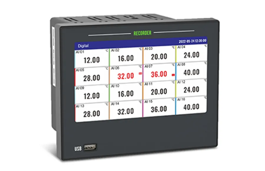
A paperless recorder is bought on three numbers — channel count, recording interval and memory — and if any one of them is wrong, the data you need at the end of the batch simply will not be there. This guide follows the sequence field engineers actually use: count and classify your inputs, choose a recording interval against your process dynamics and reporting deadline, then size the memory with a retention formula you can check yourself.
Most specification mistakes are not engineering mistakes. They are arithmetic mistakes made at the quotation stage, when nobody has time to sit down and multiply channels by samples per day. The rest of this article is that multiplication, written out, plus the interface and configuration details that decide whether the recorder talks to the rest of your plant or sits in the panel as an expensive display.
Why Paperless Recorder Projects Fail After Commissioning
Recorders rarely fail on accuracy. They fail on data continuity — the panel starts logging, the process runs for three weeks, and then someone opens the trend screen and finds that the oldest data has already been overwritten, or that the 4–20 mA signal they need on the DCS was never retransmitted because the output card was left off the order.
Two failure modes cover most cases:
Memory undersized for the interval.
1. A 1-second interval across 32 channels generates roughly 2.76 million samples per day. Buy on channel count alone and you will discover the retention limit during the first long-duration trial, not before.
Data path not specified.
2. A recorder that records perfectly but cannot move data — by USB, Modbus, retransmission or print — creates manual transcription work, which is exactly what a paperless recorder is supposed to eliminate.
Both are avoidable with a five-minute calculation and a checklist. The sections below use the JUJEA R72 touch color paperless recorder (7-inch touch LCD, up to 32 isolated universal inputs) as the worked example, because its published specification sheet contains every parameter you need to run the numbers.
Step 1 — Count Your Inputs, Then Classify the Signal Types
Start with a terminal-by-terminal list of every signal entering the panel, not with a channel count. "32 channels" means nothing until you know how many are thermocouples, how many are powered 4–20 mA loops, and how many are analog outputs you intend to retransmit.
The R72 uses 3-terminal universal input blocks with full channel-to-channel isolation: terminals 1A/1B/1C are channel 1, 2A/2B/2C are channel 2, and so on. There is no jumper or option card to change — the signal type is set in firmware per channel, so one instrument can carry a mixed set of process signals.
Signal family | Available ranges | Accuracy at 25 °C |
Current | 4–20 mA, 0–20 mA, 0–10 mA, 4–20 mA √ (square-root extraction) | ±0.2 % |
Voltage (mV) | 0–20 mV, ±20 mV, 0–100 mV, ±100 mV | ±0.2 % |
Voltage (V) | 1–5 V, 0–5 V, ±5 V, 0–10 V, ±10 V | ±0.2 % |
Thermocouple | K, S, B, J, R, N, T, E, WRe3-25, WRe5-26, F1, F2 | ±2 °C (K, J, T, E, F1, F2); ±3 °C (S, N; R above 100 °C); ±5 °C (B below 500 °C, WRe types) |
RTD | Pt100, Cu50, Cu53, Cu100 | ±0.5 °C |
Frequency (customized) | 0–10,000 Hz | 1 Hz |
Simulation | Sin, Cos | — |
Three details on that table decide whether the quote matches the plant:
Channel accuracy depends on the sensor.
The 0.2 % figure is the electrical input specification — overall instrument accuracy is stated as 0.2 % F.S. On a type K thermocouple input, the ±2 °C channel error is quoted separately because sensor and cold-junction error dominate at that point. When you compare recorders, check whether the headline figure is percent of full scale or percent of reading; they are not interchangeable, and recorders are usually specified F.S.
Square-root extraction is a channel setting, not an external device.
Frequency input is a customized option.
Two other recommendations that fall out of this step: order a spare channel or two beyond your terminal list (re-tagging a channel is a firmware action, re-ordering a recorder is not), and keep the mixed-signal capability in mind when sizing — one 32-channel unit often replaces three single-purpose instruments, but only if every signal family you need is on the built-in list.
Step 2 — Choose the Recording Interval Against the Process and the Deadline
The recording interval is the single parameter that decides how much of the process you can see and how far back you can look. It is a trade-off with no free side: every halving of the interval doubles the stored data volume.
The R72 supports recording intervals of 1 s, 2 s, 5 s, 10 s, 15 s, 30 s, 1 min, 2 min, 5 min, 10 min, 30 min and 1 h. The sampling period of the input hardware is 1 second across all channels, and the analog accuracy figure applies at 25 °C after a 30-minute warm-up.
How to choose, practically:
Match the interval to the fastest event you must prove.
Work backwards from the reporting requirement.
Check the audit or batch-cycle length.
Do not forget the fast channels inside a slow process.
One behaviour worth designing around: changing the recording interval does not erase stored history. Adjusting the clock forward, however, does overwrite overlapping records, and no historical data is generated while the unit is powered down. Set the clock and time zone before the first data campaign, not after.
Step 3 — Size the Memory With a Retention Formula
Memory is where quotations go wrong, because the storage figure on a datasheet and the retention figure your process needs are two different numbers. The bridge between them is a formula you can run on a calculator before you sign the order.
Retention follows directly from the number of records the instrument generates per day:
records per day = channel count × (86,400 ÷ recording interval in seconds)
retention (days) = usable record capacity ÷ records per day
Applied to the R72's published retention table (64 MB internal memory, cyclic overwrite), retention scales as 320 × recording interval (s) ÷ channel count — which is the same arithmetic written as a rule of thumb. Note that the channel bands in the table below are quoted at the band's upper count, and the 17–24 channel row is rounded, so use the formula to estimate your exact count and confirm the figure with the supplier:
Recording interval | 1 ch | 2 ch | 3–4 ch | 5–8 ch | 9–12 ch | 13–16 ch | 17–24 ch | 25–32 ch |
1 s | 320 d | 160 d | 80 d | 40 d | 26 d | 20 d | 16 d | 10 d |
5 s | 1,600 d | 800 d | 400 d | 200 d | 133 d | 100 d | 80 d | 50 d |
10 s | 3,200 d | 1,600 d | 800 d | 400 d | 266 d | 200 d | 160 d | 100 d |
1 min | 19,200 d | 9,600 d | 4,800 d | 2,400 d | 1,600 d | 1,200 d | 960 d | 600 d |
Worked example. A 12-channel line running at a 5-second interval generates 12 × (86,400 ÷ 5) = 207,360 records per day, and the table gives roughly 133 days of retention at that setting. Drop the interval to 1 second and the same 12 channels consume about 1.04 million records per day, cutting retention to around 26 days. The channel count did not change and the instrument did not change — only the interval did, and it cost you a factor of five in history depth.
Treat the table as a scaling rule and confirm the figure for your exact channel count and interval on the quotation, because usable capacity also depends on firmware allocation, whether accumulation is enabled, and how much of the memory the alarm, power-down and operation logs are using. Those three logs hold 256 entries each and are stored circularly, so an installation with heavy alarm traffic will rotate them faster than a quiet one.
Four memory behaviours to design around, all documented for this platform:
History is stored as a percentage of range.
Storage is internal.
Cyclic overwrite is the default behaviour.
Power-down periods produce no data.
Gaps are visible rather than interpolated, and each power cycle is logged with power-down time, power-up time and duration, which is useful evidence when you need to explain a flat line in a trend.
Step 4 — Plan How the Data Leaves the Panel
Recording is only half of the instrument's job; the other half is delivering the file or the register to whoever needs it. Plan all four paths at the specification stage so the wiring and the software license are in the quotation.
USB export. A USB flash drive inserted in the port triggers the transfer interface automatically; data can be exported in whole or in part. Files are named from device name, date and serial number (for example 01#(180904A).PLR), land in the PLR folder at the root of the drive, and are opened by the PLR.EXE data management software supplied with the recorder. Each file carries historical data, power records, alarm records and operation logs together. The port is USB 2.0 and supports drives up to 32 GB formatted FAT32. An automatic export can be scheduled to run once per day at a configured time, which is the difference between a weekly manual chore and a hands-off data pipeline.
RS485 with Modbus RTU. The RS485 port (A/B/G, wired as 485A+/485B−/GND) speaks standard Modbus RTU. Slave address is settable from 1 to 247 (0 for broadcast), baud rate from 9,600 to 115,200 (default 9,600), and parity can be set to none, odd or even. Real-time channel values are exposed as 32-bit floats in holding registers, two registers per channel — full polling examples are in our paperless recorder Modbus register map:
Channel | Register | Channel | Register | Channel | Register |
CH1 | 40001 | CH9 | 40017 | CH17 | 40033 |
CH2 | 40003 | CH10 | 40019 | CH18 | 40035 |
CH3 | 40005 | CH11 | 40021 | CH19 | 40037 |
CH4 | 40007 | CH12 | 40023 | CH20 | 40039 |
CH5 | 40009 | CH13 | 40025 | CH21 | 40041 |
CH6 | 40011 | CH14 | 40027 | CH22 | 40043 |
CH7 | 40013 | CH15 | 40029 | CH23 | 40045 |
CH8 | 40015 | CH16 | 40031 | CH24 | 40047 |
Reading channel 1 with function code 03 looks like this:
Request: 01 03 00 00 00 02 C4 0B
Response: 01 03 04 00 00 41 A4 CB D8
Payload: 00 00 41 A4 → 20.50
Note the two conventions that trip up integrators: the register address on the wire is offset from the 4xxxx reference (40001 → 0x0000), and 4-byte data uses a default byte-swap of 2143, which is configurable if your master expects the opposite order. If your application runs more than 24 channels, ask the supplier for the extended register map rather than extrapolating it.
Ethernet with Modbus TCP. The 10/100Base-T RJ45 port uses standard Modbus TCP on port 502, with IP, mask and gateway set from the configuration menu (defaults 192.168.1.30 / 255.255.255.0 / 192.168.1.1). The documented limit is three simultaneous connections — enough for a SCADA node plus an HMI, but not for a plant-wide polling scheme. Both interfaces can be configured at the same time, so a common arrangement is RS485 for the control system and Ethernet for the historian.
Analog retransmission. Up to 8 channels convert a live input value back into a 4–20 mA output (load ≤750 Ω, 0.2 % accuracy) for a PLC, DCS or a legacy chart recorder you are not ready to retire. Each output has its own source channel and a linear adjustment of the form PV = PV × K + B.
Hard copy. A TTL interface supports an optional micro printer for automatic or manual printing of digital values or curves — automatic printing can run on selected channels, with a data interval from 1 to 480 minutes or a curve interval from 1 to 480 seconds, and up to three printable titles. Hard copy is rarely the primary record any more, but some quality procedures still require a signed strip at the end of a shift.
Step 5 — Confirm the Alarm and Auxiliary Power Budget
Alarm contacts and 24 VDC loops are the two outputs most often forgotten in a quotation, and both are limited resources.
The R72 provides up to 16 normally open relay outputs rated 250 VAC 3 A or 30 VDC 3 A for resistive loads, with COM as the common terminal for each pair. Alarm configuration is per channel: lower limit, upper limit, or lower plus upper, each mapped to relay contacts that can be shared. Two parameters make the difference between a usable alarm and a nuisance trip:
Hysteresis
set as an absolute positive value. With an upper set point of 100 m and hysteresis of 1 m, the contact pulls in at 100 m and releases at 99 m — without it, a signal sitting on the set point chatters the relay.
Delay time
For the contacts themselves, check the load type. The 3 A rating is for resistive loads; a contactor coil or any inductive load needs either a derated figure from the supplier or an interposing relay, plus appropriate suppression.
The instrument also provides two 24 VDC output loops (P1+/P1−, total output current ≤120 mA) that can power a small number of field devices. A two-wire transmitter typically draws more than 20 mA, so a 120 mA budget covers a handful of loops — power the rest from a dedicated supply rather than overloading the recorder's auxiliary output.
Step 6 — Use the Channel Layer Before Blaming the Sensor
A recorder with nothing but recording functions forces you to fix signal problems in the field. Channel-level processing lets you correct them in configuration, and it costs nothing extra.
Channel setting | Range | Typical use |
Linear adjustment | PV = PV × K + B (default K = 1, B = 0) | Trim a sensor offset or scale a raw signal against a reference instrument |
Low signal cut-off | 0.0–10.0 % of range | Force zero on a noisy near-zero reading instead of printing residual noise |
Inertia filter | 0.0–9.9 s | Damp spikes on a fast, jittery signal so the trend shows the process, not the noise |
Accumulation (totalizer) | Max 99,999,999.999; coefficient 1.0 for X/h, 60 for X/min | Totalize flow channels against instantaneous engineering units |
Channel tag and unit | 16 letters / 8 characters, unit editable to 8 characters | Label channels so the export file is self-documenting |
Range and decimal point | −999,999 to 999,999 with 0–3 decimals | Match the displayed resolution to the measurement, not to the maximum |
Copy and paste | Channel to channel | Configure 32 channels in the time it takes to configure one |
Channel activation and colour | Per channel | Hide unused channels from the trend screen and colour-code groups |
If totalizing flow is the main job rather than one channel among many, it is worth comparing a dedicated flow totalizer against a recorder with accumulation enabled — the recorder gives you the trend and the event log in the same box, while a totalizer gives you a purpose-built display for batch and custody work.
Also worth knowing before the first commissioning day: signal-disconnection handling is selectable (drive to lower limit, upper limit, hold last value, or display ####, which is the default burnout indication), and ---- on the display is an overload alarm, meaning the value has exceeded the upper end of the configured range. Both are configuration checks, not hardware faults.
Step 7 — Check the Installation Envelope
Recorders are specified at the desk and installed in the panel, so the last pass is physical and electrical.
Panel mounting, indoor.
Cut-out 138 × 138 mm, body 187 × 147 × 145 mm, net weight 1.1 kg, panel protection IP65. Confirm the depth behind the panel before you quote a 145 mm enclosure.
Power.
100–240 VAC 50 Hz (L/N, non-polarized) or 24 VDC ±10 % with reverse-connection protection; capacity ≤20 W. Order the correct variant — the manual warns explicitly that the wrong supply type damages the instrument.
Grounding.
The PE terminal must be grounded before wiring. This is not optional; it is part of the instrument's protection concept.
Withstand and EMC.
AC 220 V build: 1,500 V between terminal and ground, DC 24 V build: 500 V, and 1,000 V between isolated terminals. Electrical fast transient immunity is 2,000 V on the power supply and 1,000 V on signal lines; ESD is 4,000 V contact and 8,000 V air. Insulation resistance is quoted as 20 MΩ at 500 V DC (AC build) and 5 MΩ at 100 V DC (DC build).
Environment.
Operating range −10 to 60 °C, 0–85 % RH non-condensing. Give the panel ventilation if the enclosure also holds drives, and remember the 30-minute warm-up before the accuracy specification applies.
Access control and backup.
Configuration is protected by a 4-digit password (default 0000, with a master password available from the manufacturer if it is forgotten). Configuration can be exported to USB and imported into another unit of the same type — do this on day one, and again after every change, so a failed unit can be replaced without re-entering 32 channels of setup. The same screen also holds the factory reset and clear-history functions, both of which erase stored data.
Common Paperless Recorder Specification Mistakes
Ordering on channel count alone.
1. Channel count without signal types tells you nothing about whether the unit can carry the mix on site.
Skipping the storage arithmetic.
2. Interval × channels decides retention, and the result is not intuitive — a 4× channel increase divides history depth by four.
Changing ranges after commissioning.
3. Because history is stored as a percentage of range, a range change re-scales old data. Record ranges in the commissioning file.
Setting the clock after the first campaign.
4. Adjusting time forward overwrites overlapping records; set time, date and device ID before logging starts.
Treating three Ethernet connections as a plant-wide gateway.
5. Plan RS485 and Ethernet deliberately, and split polling duties between them.
Switching an inductive load with the alarm relay.
6. The 3 A rating is for resistive loads only.
Assuming accuracy holds everywhere.
7. The figure is specified at 25 °C after warm-up; a panel at 55 °C is a different measurement environment.
No export schedule and no configuration backup.
8. Cyclic overwrite is silent, and a recorder with no backup of its setup is a two-day rebuild after a failure.
Specification Checklist
Question | Why it matters | What to confirm with the supplier |
How many signals, by type? | Determines the channel count and the input options you need | Channel count, signal families, isolation between channels |
What is the fastest signal? | Sets the recording interval, which sets storage consumption | Available intervals and the hardware sampling period |
How long must the oldest record survive? | Determines whether the memory is adequate | Retention table for your exact channel count and interval |
Where does the data go? | USB, Modbus RTU, Modbus TCP, 4–20 mA, print | Protocols, register map, simultaneous connection limit |
How many alarm contacts, switching what? | Contact count and load type | Relay rating for resistive vs inductive loads |
How much auxiliary power is needed? | 24 VDC budget is shared across loops | Total output current available |
What is the panel environment? | Temperature, humidity, depth, ingress protection | Panel cut-out, depth, IP rating, operating range |
How will the unit be replaced if it fails? | Downtime after a failure | Configuration export/import and password recovery |
Frequently Asked Questions
Q: What is the difference between a paperless recorder and a data logger?
A: Both store process signals, but a paperless recorder is built for the panel: it displays live values, bar graphs and trends on its own screen, records alarm and power-down events, and provides local operator interaction. A data logger usually has no display and depends entirely on a host system for configuration and viewing. If operators need to read values at the panel and you need an event trail, specify a recorder.
Q: How many input channels does the R72 paperless recorder support?
A: Up to 32 analog channels on the standard build, using 3-terminal universal input blocks with channel-to-channel isolation. Each channel can be configured in firmware for current, voltage, millivolt, thermocouple, RTD or frequency signals, so one unit can carry a mixed signal set. Optional functions are ordered separately: up to 16 alarm relays, up to 8 analog retransmission outputs, and the micro printer interface.
Q: How fast can a paperless recorder record?
A: The R72 records at intervals from 1 second to 1 hour, and its input hardware samples every channel once per second. Choose the interval against the fastest event you need to document: a useful rule is at least five samples across the shortest transient you care about. Slower intervals buy much longer retention — see the retention table above.
Q: How long can a paperless recorder store data?
A: Retention depends on how many channels you record and how often. Estimate it as retention (days) ≈ 320 × recording interval in seconds ÷ channel count, which matches the published figures for this 64 MB platform: 12 channels at 5 seconds gives roughly 133 days, while the same 12 channels at 1 second gives about 26 days. Because the published table is quoted per channel band, confirm the figure for your exact channel count and interval on the quotation.
Q: Can a paperless recorder send data to a PLC or SCADA system?
A: Yes. The R72 provides RS485 with Modbus RTU (slave address 1–247, baud rate up to 115,200) and a 10/100Base-T Ethernet port with Modbus TCP on port 502, supporting up to three simultaneous connections. Live channel values are available as 32-bit floats from holding register 40001 onward, two registers per channel. Up to 8 analog outputs can also retransmit a channel as 4–20 mA (load ≤750 Ω).
Q: What happens to recorded data if the power fails?
A: Stored history is retained across power loss; no new data is generated while the unit is off, so the trend shows a gap rather than interpolated values. Each power cycle is logged with power-down time, power-up time and duration — 256 power records, 256 alarm records and 256 operation log entries are kept in circular storage. For long outages, configure a daily automatic USB export.
Q: Do I need a printer with a paperless recorder?
A: Usually not — USB export, Modbus and network access cover most reporting. A TTL micro printer remains useful where a shift report must be signed on paper: the R72 can print digital values or curves automatically or on demand, for selected channels, with a data interval of 1–480 minutes or a curve interval of 1–480 seconds and up to three printed titles.
Q: Are paperless recorders suitable for regulated environments such as GMP or 21 CFR Part 11?
A: That depends on the specific requirement, not on the hardware category. The R72 provides password-protected configuration, operation logs, alarm and power-down records and exportable configuration files. Frameworks such as 21 CFR Part 11 or GMP Annex 11 also expect controls such as individual user accounts, electronic signatures and tamper-evident audit trails. Map your requirement against the specification with your QA team and the supplier before purchase.
Need Help Sizing a Recorder for Your Line?
Most specification problems are solved by two numbers: how many channels you actually need, and how long the history has to survive. Send us your signal list, the fastest event you need to capture, and how long your records must be retained — our engineers will run the retention calculation, confirm the input options and send a configuration that matches the panel, not a generic datasheet.
Request a sizing calculation · Browse paperless recorders
About the Manufacturer
This guide is published by Jujie Automation (Anhui Jujie Automation Technology Co., Ltd.), a National High-Tech Enterprise founded in 2016 and specializing in process measurement and automation instrumentation for 10+ years. Our product portfolio covers flow meters, pressure and temperature instruments, level instruments, water quality analyzers, recorders and batch filling control systems, and calibrated in our in-house flow calibration laboratory with traceable data on every unit.
Quality and compliance: ISO 9001, ISO 14001 and ISO 45001 management systems, CE, ROHS, TUV and SGS certification, and a five-stage quality process that includes 100 % incoming material inspection, individual calibration, 72-hour burn-in under temperature extremes and EMI stress, and a unique serial number for full lifecycle traceability. Products are in service with more than 350,000 customers across 160+ countries, backed by a 18-month warranty, a one-hour response commitment and lifetime maintenance support.
Editorial note: all technical parameters in this article are taken from the R72 touch color paperless recorder user manual. Where a figure depends on configuration (retention, relay load type, auxiliary power budget), we have said so rather than quoting a single number.
Ethan Liu
Ethan Liu is JUJEA's technical content specialist, translating complex sensor integration and industrial automation concepts into practical insights for engineers, system integrators, procurement professionals, and decision-makers worldwide.


 한국어
한국어 français
 Deutsch
 Español
 italiano
 русский
 português
 العربية
 tiếng việt
 čeština