Two settings decide whether a panel alarm protects your process or trains operators to ignore it: hysteresis and delay time. Neither is difficult to configure, and both are usually left at whatever the commissioning engineer typed in a hurry. This article shows how to derive both values from the trend data the recorder already has, using the alarm parameters of the R72 touch color paperless recorder as the example.
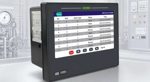
The alarm list stores channel, alarm type, status and timestamp for every event: this is the screen that tells you whether the hysteresis setting is doing its job.
Why Alarms Chatter, and Why It Costs Money
A channel alarm compares a value against a threshold. When the value sits exactly at that threshold — which is exactly where a value sits when the set point was chosen well — signal noise carries it above and below the limit several times a minute. Without damping, that produces:
- Relay chatter. Each transition is a mechanical operation of the contact. A relay switching twice a minute is switching roughly 1,000 times a day, and it is also switching whatever is connected to it.
- Alarm-log churn. The R72 stores 256 alarm records in circular storage, with each entry carrying channel, type, status and time. A chattering alarm fills that log with one event, so the record of the event that actually mattered has already been overwritten.
- Operator desensitisation. When the annunciator goes off constantly, the correct response gets slower, not faster. This is the most expensive failure mode of all, because it is invisible until it matters.
- Interlock trips. If the relay input is wired into a control system, a chattering contact looks like a rapid sequence of process events, and some control logic will act on it. If the control system reads the same channel over Modbus instead of through contacts, the chatter arrives as a stream of value transitions, which is worth understanding before you write the alarm logic — see reading channel values over Modbus.
Hysteresis and delay time exist precisely to stop this. They are not "smoothing" features; they are the difference between a signal crossing a line and a process reaching a state.
The Two Parameters, and What Each One Fixes
Alarm configuration in the recorder is per channel: lower limit, upper limit, or both, with a relay contact assigned to each condition. Two parameters then shape how that comparison behaves.
| Parameter | How it is set | What it fixes | What it costs |
|---|
| Hysteresis | An absolute value, positive only, in the channel's engineering units | Removes the "chatter zone" around the set point by separating the switch-on and switch-off points | Nothing in response time; the alarm still trips at the set point |
| Delay time | A time value, applied after the alarm condition appears | Removes short excursions that do not represent a real process state | Genuine response lag equal to the delay, every time |
The documented example makes the arithmetic concrete. With an upper set point of 100 m and a hysteresis of 1 m, the relay pulls in at 100 m and releases at 99 m. There is no separate "reset alarm at" field to configure — the hysteresis value is the reset, applied on the other side of the set point.
This has a consequence that catches people out on the low side: hysteresis is one-directional, so for a lower-limit alarm the reset point sits above the set point. If your alarm is "level must not fall below 12 percent" with a hysteresis of 1 percent, the relay energises at 12 percent and releases at 13 percent. Document which side of the set point each contact resets on, or the first maintenance technician to test the alarm will report it as faulty.
Setting Hysteresis From Your Own Noise Figure
You do not have to guess. The recorder shows you the noise, and hysteresis should be larger than it.
- Display the raw signal. Press the navigation bar's debug button to show the original analog signal value for the channel. This is the value before scaling and channel processing, and it is the honest measure of what the input is doing.
- Read the peak-to-peak spread over a normal period. On the trend screen, watch one full cycle of whatever makes the signal move — an agitator start, a compressor load change, a shift change.
- Set hysteresis at or above that peak-to-peak value, not below it.
Worked example. A pressure channel on a 0–100 m range reads between 99.4 m and 100.6 m during normal operation, so the peak-to-peak noise is 1.2 m. A hysteresis of 1 m is not enough: the signal will still cross both the 100 m and 99 m points. A hysteresis of 1.5 m gives a release point at 98.5 m and stops the chatter.
| Peak-to-peak variation at the set point | Minimum practical hysteresis | Result |
|---|
| 0.3 m | 0.5 m | On at 100 m, off at 99.5 m |
| 1.2 m | 1.5 m | On at 100 m, off at 98.5 m |
| 3.0 m | 3.0–4.0 m | On at 100 m, off at 96–97 m |
Two constraints on how far you can push this. First, the hysteresis cannot exceed the distance between the set point and the point you actually need the alarm to distinguish — a 5 m hysteresis on a 6 m band makes the alarm almost impossible to reset. Second, if you find yourself setting a hysteresis of 10 % of range or more, the alarm is doing a job that belongs elsewhere: enable the low signal cut-off (0.0–10.0 % of range) to suppress near-zero noise, or the inertia filter (0.0–9.9 s) to damp a genuinely jittery signal before it reaches the alarm comparison. Both are channel-level settings, and both are covered in how to choose a paperless recorder.
Setting Delay Time From Process Behaviour
Delay time answers a different question: how long does the condition need to persist before it is real? The method is to bracket it between two measured numbers.
- Lower bound: the longest normal excursion. Watch a full process cycle in the trend and measure how long the value stays beyond the set point when nothing is wrong. This is the number your delay must exceed.
- Upper bound: the time you need to intervene. This is an operational decision, not a technical one. Ask the person who acts on the alarm how much warning they need to prevent damage or off-spec product. That is your ceiling.
For a tank with a sloshing surface, the longest normal excursion beyond a high-level set point might be 6 seconds, and the operator needs 30 seconds of warning before overflow risk becomes real, so a 10-second delay sits comfortably between the two bounds. For a temperature alarm on a motor winding, the excursion you want to ignore might last a fraction of a second while the intervention window is also short — which pushes the delay down and, in that case, means the noise should be handled by hysteresis or filtering instead. Delay is not a substitute for a signal that is simply too noisy to alarm on.
Delay settings also change how the alarm log reads. A delay does not remove events from the log, but it does prevent the log from being consumed by excursions that never energised a relay, which keeps the 256-record circular buffer available for real events.
Alarm Types and Relay Budget
The recorder supports lower-limit, upper-limit and combined upper-and-lower alarms per channel, with up to 16 normally open relay outputs. Each pair of relays forms a group sharing a common terminal, which is worth checking against your wiring drawing before you assume 16 independent isolated contacts.
The contact rating is 250 VAC 3 A or 30 VDC 3 A for resistive loads. A contactor coil, solenoid valve or any inductive load draws an inrush current and generates a collapsing field that a resistive rating does not cover. For those loads, use an interposing relay with suppression, or obtain a derated figure from the supplier — the datasheet number is not a general-purpose switching rating.
The arithmetic that matters at specification time is set points versus relays:
available relay contacts = 16 (shared common within each pair)
potential set points     = channels × alarm conditions per channel
With 32 channels able to carry a low limit and a high limit each, you can define far more alarm conditions than 16 relays. The practical split is between alarms that must switch something (relay assigned) and alarms that only need to be recorded and displayed (no relay). Recording costs nothing extra; relays are a finite budget. Decide the split while writing the I/O list, not during commissioning.
Commissioning and Verification
Alarm settings that have never been tested are assumptions. The R72 makes this straightforward:
- Inject a signal with a calibrator or decade box on the channel, or use the debug display to read the live raw value.
- Raise the value slowly through the set point and record the exact value at which the relay energises — it should be the set point.
- Lower it slowly and record the release value — it should be the set point minus the hysteresis (or plus, for a lower-limit alarm).
- Time the delay with a stopwatch from the moment the set point is crossed to the moment the contact closes.
- Confirm the relay actually drives its load, not just that the contact clicks.
- Write the set point, hysteresis, delay, alarm type and relay assignment into the panel documentation, and export the configuration to USB so a replacement unit can be restored from a file.
Common Mistakes
- Leaving the default hysteresis at zero because the alarm "works on the bench", where the signal is clean.
- Setting hysteresis only on the upper limit and letting the low alarm chatter unnoticed.
- Assuming hysteresis works symmetrically around the set point — it does not; the reset sits on one side.
- Using delay time to hide a noisy signal instead of filtering it, which adds real lag to a real alarm.
- Wiring an inductive load directly to the alarm contact and trading a $3 interposing relay for a $300 instrument repair.
- Assigning every set point to a relay, then discovering there are not enough contacts after the I/O list is frozen.
- Never testing the release point, so the first real alarm is also the first proof that the reset value is wrong.
Frequently Asked Questions
Q: What is alarm hysteresis and how does it work?
A: Hysteresis separates an alarm's switch-on point from its switch-off point, in the same engineering units as the channel. It is set as a positive absolute value. With an upper set point of 100 m and a hysteresis of 1 m, the relay energises at 100 m and resets at 99 m. Without it, a signal sitting on the set point will chatter the contact continuously.
Q: How do I choose a hysteresis value?
A: Measure the peak-to-peak variation of the signal at the set point, using the trend screen or the debug raw-signal display, and set hysteresis at or slightly above that figure. A channel varying between 99.4 m and 100.6 m needs about 1.5 m of hysteresis to stop chatter around a 100 m set point.
Q: What does delay time do that hysteresis does not?
A: Hysteresis stops chatter; delay time filters duration. Delay holds the relay off until the alarm condition has persisted for a set period, which removes short excursions such as a momentary surge or a surface wave. The trade-off is a real response lag equal to the delay on every genuine alarm.
Q: Does the recorder have enough relays for all my alarms?
A: It provides up to 16 normally open relays rated 250 VAC 3 A or 30 VDC 3 A for resistive loads, and alarm conditions can be defined per channel on both limits. That means more potential set points than contacts, so assign relays to the conditions that must switch equipment and leave the rest as recorded and displayed alarms.
Q: Can two channels share one relay?
A: Yes. Relay contacts can be shared, and each pair of relays forms a group with a common terminal. If two channels must be reported to the same annunciator or interlock, they can be combined on one contact — but then the alarm log, not the contact, is how you tell which channel tripped.
Q: Where are alarm events stored?
A: In a 256-entry alarm list stored circularly, with each entry carrying the channel, alarm type, status and time. Because the list is circular, a chattering alarm will overwrite earlier events, which is one reason to spend time on hysteresis and delay before commissioning rather than after.
Q: How often should alarm settings be re-verified?
A: Re-verify after any change to the channel range, signal type, linear adjustment or wiring, because all four affect the value the alarm compares against. A periodic functional test of pull-in and release points is cheap insurance, and it is usually required by the same procedures that ask you to prove the alarm log is complete.
Setting Up Alarms on a New Panel?
If you send us your channel list with the set points you intend to use, we can confirm the relay assignment, the hysteresis approach for your signal types and how many contacts your configuration actually needs — before the panel is wired.
Have your alarm list reviewed · R72 (GT72R) touch color paperless recorder
About the Manufacturer
This guide is published by Jujie Automation (Anhui Jujie Automation Technology Co., Ltd.), a National High-Tech Enterprise founded in 2016 and specializing in process measurement and automation instrumentation for 10+ years. Our product portfolio covers flow meters, pressure and temperature instruments, level instruments, water quality analyzers, recorders and turnkey control systems — manufactured in our own plant in Wuhu, Anhui, and calibrated in our in-house calibration laboratory with traceable data on every unit.
Quality and compliance: ISO 9001, ISO 14001 and ISO 45001 management systems, CE, RoHS, TUV and SGS certification, and a five-stage quality process that includes 100 % incoming material inspection, individual calibration, 72-hour burn-in under temperature extremes and EMI stress, and a unique serial number for full lifecycle traceability. Products are in service with more than 350,000 customers across 160+ countries, backed by an 18-month warranty, a one-hour response commitment and lifetime maintenance support.
Editorial note: alarm types, the hysteresis example, relay ratings, log depth and the channel-level filtering ranges are taken from the R72 touch color paperless recorder user manual. The numeric examples for hysteresis and delay are illustrative arithmetic based on that documented example, not process-specific recommendations — derive your own values from your trend data. Alarm contacts driven by inductive loads must be derated or interposed; confirm with the supplier for your load.
Ethan Liu
Ethan Liu is JUJEA's technical content specialist, translating complex sensor integration and industrial automation concepts into practical insights for engineers, system integrators, procurement professionals, and decision-makers worldwide.


 한국어
한국어 français
 Deutsch
 Español
 italiano
 русский
 português
 العربية
 tiếng việt
 čeština