A paperless recorder is easy to wire and surprisingly easy to misread over Modbus. Two things account for nearly every failed integration: register addressing, and the byte order of a 32-bit float. Both are documented, and both can be confirmed with a single test frame before you write a line of PLC code. This article walks through the map, a complete request and response pair, and the byte-swap setting that decides whether channel 1 reads 20.50 or a number you will not recognise.
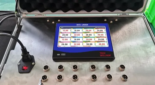
The paperless recorder with 16 channels active and M12 sensor connectors on the front panel.
What the Recorder Exposes Over Modbus
The R72 touch color paperless recorder provides two communication interfaces that can be configured at the same time: an RS485 port speaking standard Modbus RTU, and a 10/100Base-T Ethernet port speaking Modbus TCP.
| Parameter | RS485 (RTU) | Ethernet (TCP) |
|---|
| Physical | A/B/G terminals (485A+, 485B−, GND) | RJ45, 10/100Base-T |
| Protocol | Modbus RTU | Modbus TCP on port 502 |
| Slave identity | Address 1–247, default 1 (0 = broadcast) | IP 192.168.1.30, mask 255.255.255.0, gateway 192.168.1.1 (defaults) |
| Speed | 9,600 / 19,200 / 38,400 / 57,600 / 115,200 baud, default 9,600 | Network dependent |
| Framing | Parity none / odd / even, default none | — |
| Byte order | Byte-swap type for 4-byte data, default 2143 | Byte-swap type for 4-byte data, default 2143 |
| Connection limit | Multi-drop bus | 3 simultaneous connections |
Both interfaces expose the same thing: the live channel values as 32-bit IEEE-754 floats in holding registers, read with function code 03. What is not in the register map matters just as much — historical trends, alarm records, power records and operation logs are not exposed as registers. Those leave the instrument through USB export, which is covered separately in USB data export from a paperless recorder. Treat the register map as a live-data interface for a PLC, SCADA node or HMI, not as an archive.
The Register Map: One Channel, Two Registers
Each channel occupies two consecutive 16-bit registers, because a 32-bit float needs 32 bits. The published map for the R72 starts at 40001 and steps by two:
| Channel | Register | Channel | Register | Channel | Register |
|---|
| CH1 | 40001 | CH9 | 40017 | CH17 | 40033 |
| CH2 | 40003 | CH10 | 40019 | CH18 | 40035 |
| CH3 | 40005 | CH11 | 40021 | CH19 | 40037 |
| CH4 | 40007 | CH12 | 40023 | CH20 | 40039 |
| CH5 | 40009 | CH13 | 40025 | CH21 | 40041 |
| CH6 | 40011 | CH14 | 40027 | CH22 | 40043 |
| CH7 | 40013 | CH15 | 40029 | CH23 | 40045 |
| CH8 | 40015 | CH16 | 40031 | CH24 | 40047 |
Three notes that prevent most integration calls:
CH2 does not start at 40002. The spacing is two because the value is 32 bits wide. A client that assumes a step of one will read the two halves of two different channels and produce nonsense.
The published map covers CH1–CH24. If your build uses more than 24 channels, request the extended map from the supplier rather than assuming the pattern continues to 40047, 40049, 40051 and so on. Confirming an address costs one email; debugging a wrong address on a live line costs a shift.
The register returns the channel's engineering value, the same number the display shows, after the channel's range, decimal point and linear adjustment (PV = PV × K + B) have been applied. That means the SCADA tag list and the recorder channel configuration are one document. The channel settings themselves — range, decimal point, filter and linear adjustment — are covered in how to choose a paperless recorder. If maintenance re-trims K and B later and nobody records it, every logged value shifts silently.
A Complete Frame, Byte by Byte
Here is the documented read of channel 1: slave address 01, function code 03, starting at protocol address 0x0000, two registers.
Request:  01 03 00 00 00 02 C4 0B
Response: 01 03 04 00 00 41 A4 CB D8
Payload:  00 00 41 A4  →  20.50
Reading the request field by field:
| Bytes | Meaning |
|---|
01 | Slave address |
03 | Function code 03 (read holding registers) |
00 00 | Starting address |
00 02 | Quantity: two registers (one channel) |
C4 0B | CRC-16/Modbus, transmitted low byte first |
And the response:
| Bytes | Meaning |
|---|
01 | Slave address |
03 | Function code echoed |
04 | Byte count: four data bytes follow |
00 00 41 A4 | The 32-bit float, two registers, wire order |
CB D8 | CRC-16/Modbus, low byte first |
Two practical points about the checksum. First, it is CRC-16/Modbus data, not the more common ASCII CRC-16; a general-purpose CRC calculator with the wrong polynomial will reject valid frames. Second, the low byte is transmitted first, so the checksum over the request's first six bytes (0x0BC4) appears on the wire as C4 0B. Before you suspect the instrument, paste the frame into a Modbus CRC calculator and confirm it — this takes thirty seconds and eliminates an entire class of false diagnoses.
Byte Order: Why That Payload Decodes to 20.50
The data bytes arrive as 00 00 41 A4. Taken as two registers in wire order, the instrument sends 0x0000 first and 0x41A4 second. Now compare with the value you expect: IEEE-754 single precision 20.5 is 0x41A40000.
In other words, the two 16-bit halves arrive reversed relative to the natural big-endian layout of the float, and rebuilding 0x41A40000 requires swapping the two words. That swap is exactly what the byte-swap parameter controls, and its default value — 2143 — is the word-swapped assembly order.
| What you do | What you get |
|---|
| Swap the two 16-bit words, then interpret as IEEE-754 | 0x41A40000 → 20.50 (correct) |
| Interpret the registers as received, no swap | A near-zero denormal or a wildly wrong magnitude — never the value on the display |
The reason this wastes so much engineering time is not that the error is subtle; it is that the error is inconsistent in its visibility. A value that comes through as a denormal near zero is spotted immediately. A float reassembled in the wrong order can decode into a large but plausible-looking number, which gets screenshotted and emailed around as a "sensor problem" before anyone checks the byte order.
The setting is configurable on the instrument, and the default 2143 suits masters that expect the device's word order. If your master library already performs its own word swap, you have two swaps and therefore none — set one end only, and verify against the display with a known input. A 4–20 mA loop at exactly 12.00 mA on a channel configured 0–100 is a clean reference point: the register and the screen must agree.
Two Address Conventions That Cause "Illegal Data Address"
The 4xxxx notation is a human convention, not a wire value. In the frame above, CH1's starting address field is 00 00, because 40001 maps to protocol address 0 under function code 03. Clients differ: some libraries want you to type 40001, some want 0, and some want 1. Decide once, write the convention at the top of your tag list, and keep it there.
The other causes of an exception response are mundane:
Using function code 04. The documented map is read with FC03 (holding registers). FC04 addresses a different register space and will not return channel values.
Reading past the mapped range. Requests beyond the published register set generally return an exception code rather than zeros — the instrument is telling you the address is wrong, not that the process value is unavailable.
Assuming a contiguous block. Channels are contiguous in pairs; a request that starts at 40002 reads half of CH1 and half of CH2.
Polling 32 Channels Without Loading the Bus
The Modbus standard caps a single read at 125 registers. Since 32 channels occupy 64 registers, the entire instrument can be polled in one request — a two-register read per channel is inefficient and unnecessary.
| Practice | Why it matters here |
|---|
| Poll one block of 64 registers | One request instead of 32; fewer timeouts on a busy bus |
| Poll at 1–2 s, not 10 Hz | The input hardware samples every 1 second; faster polling returns duplicate values and occupies line time |
| Budget line time on RS485 | A 64-register response is roughly 140 bytes; at 9,600 baud with 8N1 framing that is around 145 ms of bus time, and at 38,400 baud around 36 ms. Add the request and any other slaves before you choose the polling rate |
| Respect the three-connection limit on Ethernet | A SCADA node, an HMI and an engineering laptop is exactly three; a fourth client will fail to connect, so use a store-and-forward gateway if more consumers are needed |
| Split duties between the two interfaces | RS485 for the control system, Ethernet for the historian, or the reverse — both can be configured simultaneously |
| Keep the 4–20 mA option in mind | Up to 8 channels can retransmit a live value as 4–20 mA (load ≤750 Ω), which is often the faster route for a legacy controller that does not speak Modbus |
For RS485 wiring, daisy-chain the segment rather than starring it, keep A and B consistent between devices, connect the G terminal to the signal reference of the segment, and terminate at the physical ends of the bus. Channel-to-channel isolation inside the recorder (1,000 V between isolated terminals) protects the instrument, not the integrity of a badly routed bus.
Commissioning Checklist
| Check | Setting or action | Verification |
|---|
| Slave address and baud rate | Defaults 1 and 9,600; confirm against the master's config | Read one register from the master |
| Frame convention | 40001 vs 0 vs 1 — pick one and document it | Same convention in the tag list and the client |
| Byte order | Default 2143; set on one end only | Register value matches the display at a known input |
| Sample block size | 64 registers for 32 channels | One request returns all channels |
| Poll rate | 1–2 s | No duplicate-value flooding on the bus |
| Ethernet clients | Maximum 3 | Connect the third, then test the fourth intentionally |
| Channel configuration | Range, decimal point, unit, K and B per channel | Export the configuration and file it with the tag list |
| Extended map | Request addresses beyond CH24 if used | Written confirmation from the supplier |
Common Mistakes
Reading with function code 04 instead of 03, then concluding the map is wrong.
Typing 40001 into the address field on the wire instead of the protocol address.
Forgetting the word swap. Default byte-swap 2143 is the correct assembly for this platform; two swaps cancel out.
Polling at 10 Hz against a 1-second acquisition period, which fills the bus with duplicates.
Extrapolating addresses past CH24 instead of asking for the extended map.
Looking for history in registers. Trends, alarm records, power records and operation logs are exported to USB, not exposed as registers.
Connecting a fourth Ethernet client and blaming the network.
Filing the tag list without the channel configuration, so a later K/B change silently shifts every tag.
Frequently Asked Questions
Q: Which Modbus function code does the recorder use for channel data? A: Function code 03, read holding registers. The manual documents the channel map under the 4XXXX reference range, so the example for channel 1 starts at 40001. A client that polls FC04 returns data from a different register space and will not produce channel values. Confirm the function code first whenever a poll times out or returns an exception.
Q: What register holds channel 1, and where does channel 2 start? A: Channel 1 is at 40001 and channel 2 is at 40003, because each value is a 32-bit float occupying two registers. The published map runs to CH24 at 40047 in steps of two. If your unit uses more than 24 channels, ask the supplier for the extended map instead of extrapolating the pattern.
Q: Why is the value I read back completely wrong? A: Byte order. The two 16-bit halves of the float arrive swapped relative to the big-endian layout, which is why the default byte-swap setting is 2143. Apply the swap on one end only, then verify against the display with a known input such as 12.00 mA on a 0–100 channel. Two swaps cancel out and put you back where you started.
Q: How many channels can I read in a single request? A: All of them. The Modbus standard caps one read at 125 registers, and 32 channels occupy 64 registers, so the entire instrument fits in one FC03 request. Polling one channel per request wastes bus time and multiplies timeout risk on a shared RS485 segment. Use one block read at a 1–2 second interval.
Q: Can I read historical data or the alarm log over Modbus? A: No. The register map exposes live channel values only. Historical trends, alarm records, power records and operation logs are exported through the USB port as a .PLR file, which contains all four data sets. The instrument also keeps 256 alarm records, 256 power records and 256 operation log entries in circular storage for on-screen review.
Q: How many Ethernet clients can connect at once? A: Three simultaneous connections over Modbus TCP on port 502. That covers a SCADA node plus an HMI, but not a plant-wide polling scheme. If more consumers need the data, poll the recorder with one gateway or historian and redistribute from there, or use the RS485 port in parallel — both interfaces can be configured at the same time.
Q: What are the RS485 default settings? A: Slave address 1, 9,600 baud, no parity, byte-swap type 2143. Addresses 1–247 are valid, with 0 reserved for broadcast; baud rates of 9,600, 19,200, 38,400, 57,600 and 115,200 are supported, and parity can be set to none, odd or even. Record the settings you choose on the panel schedule and in the tag list.
Q: What accuracy and refresh rate should I expect from a polled value? A: The value reflects the channel's configured range and its linear adjustment. Electrical accuracy for current and voltage inputs is specified at ±0.2 %, with overall instrument accuracy quoted as 0.2 % F.S. at 25 °C after a 30-minute warm-up. The input hardware samples every channel once per second, so polling faster than 1 second returns duplicates.
Need the Register Map for Your Build?
If you are integrating a recorder into an existing SCADA or PLC project, we can supply the register map for your exact channel count, confirm the byte-order convention your master expects, and check your polling plan against the instrument's 1-second sampling period. Send us your channel list and the master you are using.
Request the register map for your configuration · GT72R touch color paperless recorder
About the Manufacturer
This guide is published by Jujie Automation (Anhui Jujie Automation Technology Co., Ltd.), a National High-Tech Enterprise founded in 2016 and specializing in process measurement and automation instrumentation for 10+ years. Our product portfolio covers flow meters, pressure and temperature instruments, level instruments, water quality analyzers, recorders and turnkey control systems — manufactured in our own plant in Wuhu, Anhui, and calibrated in our in-house calibration laboratory with traceable data on every unit.
Quality and compliance: ISO 9001, ISO 14001 and ISO 45001 management systems, CE, RoHS, TUV and SGS certification, and a five-stage quality process that includes 100 % incoming material inspection, individual calibration, 72-hour burn-in under temperature extremes and EMI stress, and a unique serial number for full lifecycle traceability. Products are in service with more than 350,000 customers across 160+ countries, backed by an 18-month warranty, a one-hour response commitment and lifetime maintenance support.
Editorial note: register addresses, interface parameters and the request/response example are taken from the R72 touch color paperless recorder user manual. Line-time figures in the polling section are arithmetic estimates for the stated baud rates and framing, not measured values. If your application needs more than 24 channels or a custom map, confirm the addresses with the supplier before commissioning.
Ethan Liu
Ethan Liu is JUJEA's technical content specialist, translating complex sensor integration and industrial automation concepts into practical insights for engineers, system integrators, procurement professionals, and decision-makers worldwide.


 한국어
한국어 français
 Deutsch
 Español
 italiano
 русский
 português
 العربية
 tiếng việt
 čeština