How accurate is your recorder's temperature reading? The channel figure on the datasheet (±0.5 °C for a Pt100, around ±2 °C for a type K thermocouple) is only one of five error terms in the loop, and in most installations it is not the largest one. This article compares thermocouple and RTD inputs as they behave on a recorder's universal input, then assembles an accuracy budget you can fill in with your own sensor datasheets.
The examples use the GT72R touch color paperless recorder, whose input block accepts both families on the same 3-terminal channel — the signal type is selected per channel in firmware, so a single 32-channel unit can carry thermocouples, RTDs, 4–20 mA and voltage signals side by side without option cards.
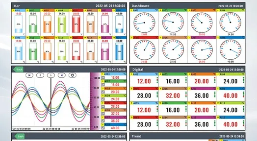
One instrument, four ways to read the same channels: bar graph, dashboard, trend curve and digital value views. The display mode changes how a value is drawn, not how it was measured - the accuracy budget applies to all four.
The Two Families at a Glance
The documented input accuracy figures for this platform, measured at 25 °C after a 30-minute warm-up:
| Family | Type and range | Accuracy |
|---|
| Thermocouple | K: −200 to 1,372 °C | ±2 °C |
| J: −210 to 1,000 °C | ±2 °C |
| T: −200 to 400 °C | ±2 °C |
| E: −200 to 1,000 °C | ±2 °C |
| N: −200 to 1,300 °C | ±3 °C |
| S: −50 to 1,768 °C | ±3 °C |
| R: −50 to 100 °C | ±4 °C; 100 to 1,768 °C |
| B: 250 to 500 °C | ±5 °C; 500 to 1,820 °C |
| WRe3-25: 0 to 2,315 °C, WRe5-26: 0 to 2,310 °C | ±5 °C |
| F1, F2: 700 to 2,000 °C | ±2 °C |
| RTD | Pt100: −200.0 to 650.0 °C | ±0.5 °C |
| Cu50: −50.0 to 140.0 °C | ±0.5 °C |
| Cu53, Cu100: −50.0 to 150.0 °C | ±0.5 °C |
Two readings of this table are easy to get wrong.
First, the thermocouple figure is absolute, so its relative weight changes with temperature. A ±2 °C channel error on a K-type input is 0.2 % of a 1,000 °C reading but 1 % of a 200 °C reading. The same channel is "accurate" or "coarse" depending entirely on where in its range you operate. RTD channels behave similarly — ±0.5 °C is 0.08 % at 650 °C and 0.5 % at 100 °C.
Second, the range limits are structural. Pt100 stops at 650.0 °C and the copper RTDs stop at 150 °C. Below about 600 °C you have a choice; above it, you are on a thermocouple. Above roughly 1,400 °C, you are on S, R, B or a tungsten-rhenium type, all of which carry a wider channel error than a K-type. Selection at high temperature is a materials decision first and an accuracy decision second.
Where the Rest of the Error Comes From
A recorded temperature is the sum of at least five contributions. Only one of them is the channel figure.
| # | Error term | Where the number comes from | How to reduce it |
|---|
| 1 | Sensor element tolerance | The sensor datasheet and its tolerance class under the applicable standard — IEC 60584 for thermocouples, IEC 60751 for platinum RTDs | Buy a tighter class; for Pt100 that usually means moving from a standard class to a precision class |
| 2 | Cold junction compensation (thermocouples only) | The instrument's built-in cold junction sensor, corrected at commissioning | Verify it against a reference and apply the automatic-mode correction |
| 3 | Wiring and lead error | Extension or compensating cable grade for thermocouples; lead resistance for a 2-wire RTD | Use the correct grade of compensating cable; keep RTD lead resistance out of the measurement |
| 4 | Input channel error | The table above — for example ±2 °C on K, ±0.5 °C on Pt100 | Choose the input type whose range and error suit the loop |
| 5 | Installation and process error | Immersion depth, thermal contact, radiation, conduction along the sheath | Fix the installation, because this term usually dominates and is invisible on a datasheet |
Two notes on the middle terms, because they cause most of the surprises.
Cold junction compensation. A thermocouple measures a temperature difference between its tip and its terminals, so the terminal temperature has to be known. The recorder has its own temperature sensor for this and defaults to automatic compensation, with a manual setting available for special circumstances. In automatic mode, tapping the displayed cold junction temperature lets you enter the accurate value as a correction; a long press clears the correction. The practical warning is that the sensor measures the terminal block, not the process and not necessarily the cabinet: put a heat source, a draught or a hot gland plate next to the terminals and the cold junction reading becomes a hypothesis. This is worth checking once at commissioning with the panel closed and at working temperature, not on an open panel in a workshop.
Compensating cable and lead resistance. A thermocouple must be extended with cable of the correct type, not with ordinary copper — the extension wire is part of the measurement circuit, and it carries its own tolerance. An RTD behaves in the opposite way: it is a resistance measurement, so ordinary copper is fine but the resistance of that copper adds to the reading. A 2-wire RTD connection therefore includes the lead resistance in the result. The recorder's input block is a 3-terminal design; if your loop needs the lead resistance taken out of the measurement, confirm the wiring scheme supported for your build before you specify the sensor.
Assembling the Budget
Two ways to combine the five terms, and the choice matters when you are asked to prove a number:
worst case     = e1 + e2 + e3 + e4 + e5

                (all errors at their limit, all pointing the same way)


root-sum-square ≈ sqrt(e1² + e2² + e3² + e4² + e5²)

                (independent random errors, typical behaviour)
Worked example — a type K thermocouple on a channel reading 400 °C. The channel term is taken from the table above; the other three are placeholder values you would replace with your sensor datasheet and cable grade:
| Term | Placeholder value | Source |
|---|
| Sensor element tolerance (K) | ±1.5 °C | assumed for this example — take from your sensor datasheet |
| Cold junction compensation | ±0.5 °C | assumed — verify at commissioning |
| Compensating cable | ±0.5 °C | assumed — cable grade dependent |
| Input channel (K type) | ±2.0 °C | documented for this platform |
| Installation and process | ±1.0 °C | assumed — immersion and contact dependent |
worst case      = 1.5 + 0.5 + 0.5 + 2.0 + 1.0             = ±5.5 °C

root-sum-square = sqrt(2.25 + 0.25 + 0.25 + 4.0 + 1.0)     = ±2.8 °C
Run the same budget for a Pt100 on the same 400 °C loop and the channel term drops from ±2.0 °C to ±0.5 °C, while the cold junction term disappears and a lead-resistance term replaces the compensating cable term. That is the whole argument for RTDs below 600 °C, and it is why the budget — not the headline accuracy — is what a quality department should be shown.
The RSS figure is the one to quote as typical performance when the errors are independent and none of them is systematically biased. The worst-case figure is the one to quote when a tolerance has to be guaranteed. Do not present the RSS figure as a guarantee; they are different claims.
Choosing Between Them for a Given Loop
| Criterion | Thermocouple | RTD (Pt100 and copper types) |
|---|
| Practical range on this input | −210 to 2,315 °C depending on type | −200.0 to 650.0 °C (Pt100); copper types to 150 °C |
| Channel accuracy | ±2 to ±5 °C depending on type | ±0.5 °C |
| Accuracy at low temperature | Poor in relative terms | Strong — the reason RTDs dominate below 200 °C |
| Response time | Fast, especially exposed-junction designs | Slower — more mass in the element and sheath |
| Vibration and shock | More tolerant | Less tolerant |
| Lead wire | Must be the correct compensating cable | Ordinary copper is acceptable, but lead resistance matters |
| Drift over time | Higher; recalibration intervals tend to be shorter | Lower; more stable with age |
| Self-heating | None | Present, and a real consideration in still air with a high excitation current |
| Best fit | Furnaces, kilns, flue gas, high-temperature process | Process temperature, food, pharma, water, HVAC, cold chain |
A working rule: below 600 °C, choose the RTD unless something about the installation — vibration, response speed, an existing thermocouple well, or available instrumentation — argues otherwise. Above 600 °C, the choice is made for you by range.
Where This Budget Actually Shows Up
A recorder channel that reads temperature usually feeds something downstream, and that is where the budget stops being academic.
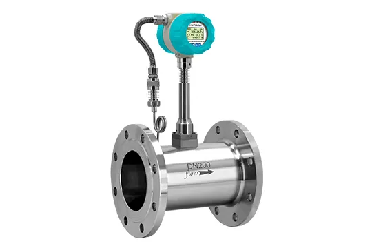
- Compensated flow measurement. A vortex meter measuring steam or gas needs the process temperature to convert a measured volume into a mass or standard-volume figure. This is the difference between a meter with and without temperature and pressure compensation: vortex flow meters with temperature and pressure compensation carry a temperature input of their own, and every degree of error there propagates into the compensated total.
- Heat and energy metering. A heat meter is a flow measurement multiplied by a temperature difference. Ultrasonic heat meters and electromagnetic BTU meters live or die on two temperature channels and on the accuracy of the difference between them. A ±0.5 °C channel error on each of two channels is up to ±1 °C of error on the difference in the worst case, or about ±0.7 °C by root-sum-square: on a 10 °C difference that is 7 to 10 % of the measured quantity, before the flow meter has contributed anything.
- Where compensation is not needed. A thermal gas mass flow meter measures mass directly by heat conduction and does not require separate temperature or pressure compensation, which is why it is often the simpler choice for compressed air and stack gas.
The practical consequence: if the recorder is charting temperature for trend only, a wide budget is tolerable. If those channels feed a compensated total or an energy figure, the same budget becomes a number on an invoice, and the sensor class is worth paying for.
Channel-level processing is where a recorder earns its place. All of these settings are per channel:
| Setting | Range | Where it helps |
|---|
| Cold junction | Automatic (default) or manual | Thermocouple channels; correct against a reference at commissioning |
| Linear adjustment | PV = PV × K + B, default K = 1, B = 0 | Single-point trim so the recorder agrees with a reference instrument |
| Inertia filter | 0.0–9.9 s | Damps a jittery signal on a fast channel without changing the recording interval |
| Low signal cut-off | 0.0–10.0 % of range | Suppresses residual near-zero noise |
| Range and decimal point | −999,999 to 999,999 with 0–3 decimals | Match the displayed resolution to the budget |
| Unit | Up to 8 characters, default ℃ | Keeps the trend and the export self-documenting |
| Burnout action | Lower limit, upper limit, hold, or #### (default) | Defines what a broken sensor looks like on screen and to an alarm |
That last row deserves a decision rather than a default. If a broken thermocouple drives the channel to its lower limit, the failure appears as "cold", which will trip a low-temperature alarm and leave a high-temperature alarm silent — which is a setting question as much as a wiring one, and it is covered in how to set alarm hysteresis and delay time. Choosing an upper-limit action or "hold" changes which alarm tells you the sensor has failed. Either behaviour is defensible; leaving it unconsidered is not. The display convention is documented — #### indicates a disconnection and ---- indicates an overload, meaning the signal has exceeded the upper end of the configured range. All of these channel-layer settings, and how they interact with recording interval and memory, are covered in how to choose a paperless recorder.
And one caution on resolution: three decimal places do not create accuracy. Setting a K-type channel to display 0.01 °C on a budget of ±2.8 °C produces numbers that look precise and invite decisions the measurement cannot support. Set the decimal places to roughly what the budget justifies.
Verification at Commissioning
- Warm up for 30 minutes before comparing anything, because the error figures are stated at 25 °C after that warm-up.
- Check the cold junction with the panel closed and at working temperature, then apply the automatic-mode correction if needed.
- Compare at two points, not one — for example a low point near the working minimum and one near the working maximum. A single-point check hides gain errors.
- Confirm the burnout action by disconnecting the sensor and observing what the display and the alarms do.
- Record the budget — sensor class, channel type, cold junction correction, K and B values, filter and cutoff settings — with the loop documentation, so the next person can reproduce the measurement rather than re-invent it.
Common Mistakes
- Judging loop accuracy by the channel figure alone, when installation error usually dominates.
- Using ordinary copper to extend a thermocouple instead of the correct compensating cable.
- Ignoring cold junction correction and then chasing a systematic offset for weeks.
- Leaving the burnout action at its default and discovering that a failed sensor reads as a cold process.
- Displaying three decimal places on a channel with a multi-degree budget.
- Choosing a B-type thermocouple for a 300 °C application and accepting ±5 °C where an RTD would give ±0.5 °C.
- Quoting the RSS figure as a guaranteed tolerance when the customer asked for a worst-case number.
Frequently Asked Questions
Q: Is a thermocouple or an RTD more accurate on the same recorder? A: The RTD channel is more accurate: ±0.5 °C for Pt100 and the copper types, against ±2 °C for K, J, T and E thermocouples and ±3 to ±5 °C for the higher-temperature types. The gap widens in the full budget, because a thermocouple also carries cold junction compensation error and compensable-cable tolerance, while an RTD does not.
Q: What temperature range can each input handle? A: On this platform, Pt100 covers −200.0 to 650.0 °C and the copper RTDs cover roughly −50 to 150 °C, while thermocouples span from −210 °C for J-type up to 2,315 °C for WRe3-25. Above 650 °C the RTD option disappears and the choice is between thermocouple types.
Q: How does the recorder handle cold junction compensation? A: It has its own temperature sensor and defaults to automatic compensation, with a manual setting available for special circumstances. In automatic mode you can correct the reading by entering an accurate temperature on the displayed value, and a long press clears that correction. Verify it at commissioning with the panel closed and at working temperature.
Q: Why does my recorded temperature differ from a reference thermometer? A: Work through the budget: sensor tolerance, cold junction, cable, channel and installation. A persistent offset across the whole range is usually a cold junction or linear-adjustment issue, addressable with the channel's K and B correction, while an offset that grows with temperature points to a sensor class or cable grade problem.
Q: Can I mix thermocouples and RTDs on one recorder? A: Yes. The input block is a 3-terminal universal design and the signal type is set per channel in firmware, so a 32-channel unit can carry thermocouples, RTDs, current, voltage and millivolt signals together. There are no option cards to order for the standard signal set; frequency input is the customized exception.
Q: What do #### and ---- on the display mean? A: #### is the disconnection (burnout) indication and ---- is an overload alarm, meaning the signal has exceeded the upper limit of the configured range. Both are configuration checks rather than hardware faults, and the burnout action — lower limit, upper limit, hold or #### — is selectable per channel.
Q: Should I use three or four decimal places for temperature? A: Set the decimal places to match the accuracy you can actually deliver. On a loop with a ±2.8 °C budget, three decimals implies a precision that does not exist and invites decisions the measurement cannot support. One decimal place is usually the honest presentation for a process temperature channel.
Need Your Accuracy Budget Reviewed?
Send us the loop list with the sensor type, the range and the tolerance class of each sensor, and we will return the channel contributions for the recorder side, the cold junction approach for your thermocouple channels, and the wiring scheme to confirm before the sensors are ordered.
Ask for an accuracy budget review · GT72R touch color paperless recorder
About the Manufacturer
This guide is published by Jujie Automation (Anhui Jujie Automation Technology Co., Ltd.), a National High-Tech Enterprise founded in 2016 and specializing in process measurement and automation instrumentation for 10+ years. Our product portfolio covers flow meters, pressure and temperature instruments, level instruments, water quality analyzers, recorders and turnkey control systems — manufactured in our own plant in Wuhu, Anhui, and calibrated in our in-house calibration laboratory with traceable data on every unit.
Quality and compliance: ISO 9001, ISO 14001 and ISO 45001 management systems, CE, RoHS, TUV and SGS certification, and a five-stage quality process that includes 100 % incoming material inspection, individual calibration, 72-hour burn-in under temperature extremes and EMI stress, and a unique serial number for full lifecycle traceability. Products are in service with more than 350,000 customers across 160+ countries, backed by an 18-month warranty, a one-hour response commitment and lifetime maintenance support.
Editorial note: thermocouple and RTD ranges, channel accuracies, cold junction behaviour, channel settings and display conventions are taken from the GT72R touch color paperless recorder user manual. Sensor element tolerance, cable tolerance and installation error are shown as clearly labelled placeholder values, because they depend on the sensor and the installation; take them from your own datasheets. Tolerance classes are referenced by standard name (IEC 60584 for thermocouples, IEC 60751 for platinum RTDs) without quoting numeric limits, which should be read from the current edition of the standard.
Ethan Liu
Ethan Liu is JUJEA's technical content specialist, translating complex sensor integration and industrial automation concepts into practical insights for engineers, system integrators, procurement professionals, and decision-makers worldwide.


 한국어
한국어 français
 Deutsch
 Español
 italiano
 русский
 português
 العربية
 tiếng việt
 čeština