Most wastewater flow measurement faults are installation faults, not instrument faults. Municipal wastewater is conductive enough for an electromagnetic flowmeter almost everywhere in a plant, so the meter that fails is usually the one specified for the wrong point: a full-bore meter in a gravity line running half full, a 316L electrode in sulphide-laden sludge, an IP65 housing in a chamber that floods every wet season. This guide to wastewater flow measurement takes the four points where meters are most often replaced, names the failure mode at each, and gives the configuration that survives it.
Short answer: match the meter to the hydraulic condition first. Raw sewage at the inlet needs an abrasion-resistant liner and a sulphide-resistant electrode; return sludge needs a full pipe and signal damping; waste activated sludge needs a velocity band wide enough to stay above 0.5 m/s; final effluent needs a cleanable electrode and a calibration record you can defend. Conductivity is rarely the limiting factor — pipe fullness, solids and electrode fouling are.
Why Wastewater Is Hard on Flow Meters
An electromagnetic flowmeter measures velocity and multiplies by the pipe cross-section. Everything that goes wrong in wastewater attacks one of those two inputs.
Failure mode | What it does to the measurement | Where it shows up |
Pipe running partially full | Area is overestimated; reading can be far above true flow | Gravity lines, plant inlet, outlet culverts |
Rags and fibrous solids wrapping the electrodes | Signal collapses or drifts toward zero | Raw sewage, screenings bypass, storm flows |
Grit and abrasion | Liner wears through; noise and drift follow | Inlet, grit channels, pump discharges |
Sulphides and H₂S in septic sewage | 316L electrode corrodes; reading drifts low | Long gravity runs, force mains, sludge lines |
Entrained air and gas pockets | Spikes and positive bias; unstable output | Aeration returns, pump suction, high points |
Biofilm and grease films | Slow downward drift between cleanings | Final effluent, treated water, dosing lines |
Velocity below 0.5 m/s | Signal approaches the noise floor | Oversized meters, low-flow night operation |
Conductivity is the one item on this list that usually is not a problem. The theoretical minimum for electromagnetic measurement is around 5 µS/cm and the practical minimum is closer to 30 µS/cm; municipal wastewater typically sits several hundred µS/cm above that, and even biologically treated effluent stays well clear. If a meter reads nothing at all, look for an empty pipe, a failed excitation circuit or a wiring fault before questioning the medium — a water flow meter that reports zero on a live sewage line is almost never a conductivity problem.
The Six Measuring Points in a Wastewater Plant
Most plants do not need six meters, but they need six decisions. The table below is the map for wastewater flow measurement; the four scenarios that follow cover the points where specification actually goes wrong.
Point | Medium | What dominates the specification |
1. Plant inlet | Raw sewage, grit, rags, H₂S | Abrasion resistance, fouling tolerance, full-pipe location |
2. Aeration basin return | Mixed liquor, entrained air, low velocity | Full pipe, damping, position relative to air injection |
3. Return activated sludge (RAS) | 0.5–1.5% solids, abrasive | Liner wear, electrode coating, velocity band |
4. Waste activated sludge (WAS) | 0.5–3% solids, low velocity | Minimum velocity, solids ceiling, cleaning access |
5. Chemical dosing | Ferric chloride, PAC, caustic, polymer | Chemical resistance, small DN, turndown |
6. Final effluent | Low solids, biofilm, compliance use | Electrode cleanability, calibration evidence |
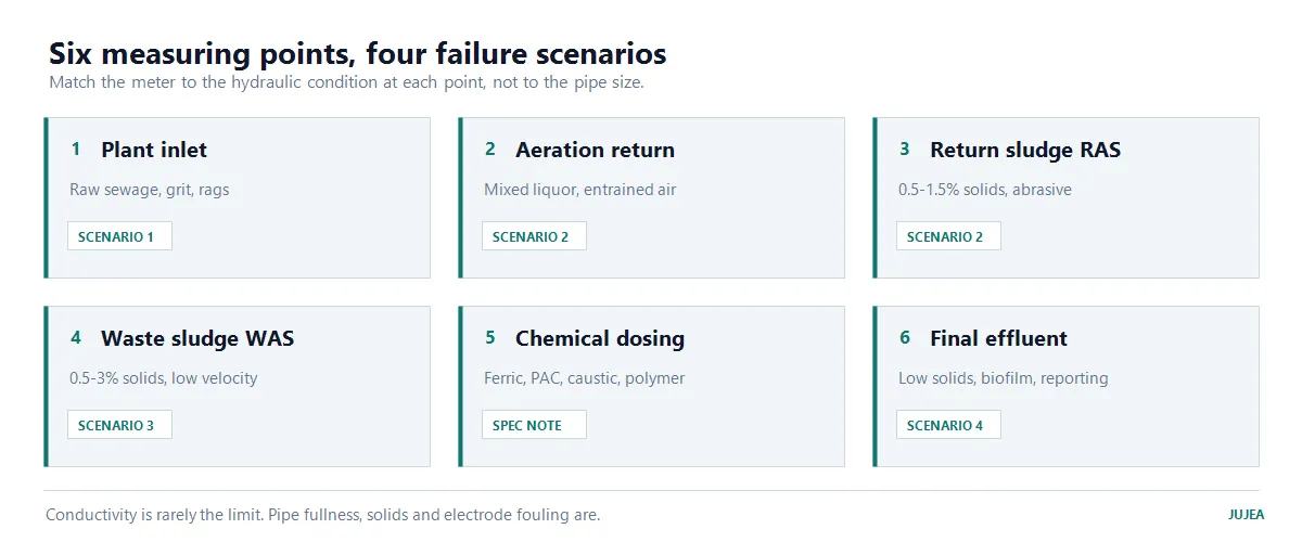
Six measuring points, four of which account for most meter replacements.
Scenario 1: Raw Sewage at the Plant Inlet
Process condition. Flow arrives from a gravity sewer or a pumping station, typically DN300–DN1200, with grit, rags, grease and, in long or warm sewers, hydrogen sulphide. Velocity in a rising main usually sits between 0.8 and 2.5 m/s.
What fails first. Two mechanisms, in this order. Grease and sulphide films coat the electrodes and the reading drifts low over weeks — operators often compensate with a correction factor instead of cleaning, which hides the problem until it is severe. Then rag material bridges the electrodes and the signal drops to zero in a single event, usually during a storm.
Configuration that holds.
Liner: hard rubber (CR). Abrasion resistance matters more than chemical resistance here. PTFE is the right choice only when the sewage carries an industrial chemical load — it resists attack but wears faster under grit.
Electrode: Hastelloy C rather than 316L. Sulphide and chloride attack 316L; the cost difference at DN600 is small against the cost of a replacement meter and a lost flow record.
Housing: IP68 if the meter sits in a wet well or a chamber that can flood. IP65 is adequate only in a dry, drained chamber — and chambers that are dry on the day of installation are not always dry in July.
Location: a full section. Prefer the discharge side of the inlet pump, or a vertical rising main. Never at the top of a horizontal gravity run, where gas collects and the pipe runs part full at low flow. An industrial wastewater flow meter sited on a gravity line that drains overnight will be wrong every morning, however good the calibration.
Grounding: grounding rings at both flanges, bonded to the pipe. A meter that uses the pipe as its ground reference reads noise, not flow.
Commissioning check. Compare against a portable clamp-on meter over a 24-hour period that includes the night minimum, not just the daytime peak. A meter that agrees at 2 m/s and disagrees at 0.4 m/s has a low-flow or fullness problem, not a calibration problem.
Scenario 2: Aeration Basin and Return Sludge
Process condition. Return sludge and mixed liquor move at low velocity, often 0.3–1.0 m/s, and carry entrained air from aeration and from pump suction. Solids are low — typically 0.2–0.4% in mixed liquor — so the medium itself is not the difficulty.
What fails first. Air. Bubbles displace liquid in the measuring section, and the meter reads high and unstable; the effect is worst when the meter sits near a pump suction or downstream of an air injection point. The secondary failure is a meter sized for peak flow that spends most of its life below 0.5 m/s, where drift and noise dominate.
Configuration that holds.
Full pipe, always. Install on the discharge side of the return sludge pump, never on a suction line and never at a high point.
Damping of 3–5 s at the converter. Raw output on an aerated line is unusable for control; damping smooths it without hiding a genuine trend.
Low-flow cut-off enabled. Below the configured threshold the output is forced to zero instead of reporting noise as flow.
Velocity band 1–2 m/s at design flow. Size for the normal operating range, not the maximum pump curve. An oversized meter on a low-velocity line is the most common sizing error in this part of the plant.
Scenario 3: Waste Activated Sludge (0.5–3% Solids)
Process condition. WAS is the hardest routine wastewater flow measurement duty in the plant: abrasive, prone to coating, and usually pumped intermittently at a velocity that falls below the reliable range whenever the pump ramps down.
What fails first. Coating, then velocity. A film of sludge on the electrodes attenuates the signal and the reading drifts low; because the drift is slow, it is often mistaken for a genuine reduction in sludge production. When the pump runs at low speed, the meter drops under 0.5 m/s and the reading becomes unstable rather than merely inaccurate.
Configuration that holds.
Liner: CR, as at the inlet. Sludge is abrasive and chemically mild.
Electrode: Hastelloy C where the sludge is anaerobic or sulphidic; 316L is acceptable in well-aerated sludge. Decide from the digester arrangement, not from the datasheet default.
Size for the pumped duty, not the pipe. A DN200 line carrying 40 m³/h runs at about 0.35 m/s and will not measure reliably; the same flow through DN150 runs at 0.63 m/s. Reducing one size is often the correct fix.
Plan for cleaning. Specify a meter whose electrodes can be reached without cutting the pipe, and put the cleaning interval in the maintenance plan at the commissioning stage.
The solids ceiling. Electromagnetic measurement remains usable in sludge up to roughly 2–3% solids, but accuracy degrades as solids rise and as velocity falls. Above that range — dewatered sludge, cake, high-solids digester feed — a different principle is the honest answer: Doppler ultrasonic for velocity in open channels, or Coriolis where mass dosing matters. For a specific duty, confirm the ceiling against the actual solids curve with the supplier rather than assuming a percentage.
Scenario 4: Final Effluent and Discharge Compliance
Process condition. Treated effluent is clean, low in solids and chemically mild. The difficulty is not the medium but the use of the number: discharge records are reported, sometimes regulated, and a meter that drifts quietly for a year creates a reporting problem rather than a maintenance ticket.
What fails first. Biofilm. A thin film on the electrodes produces a slow downward drift that is invisible day to day. The second failure is documentary: no baseline comparison, no calibration certificate, no record of when the zero was last checked.
Configuration that holds.
Full-bore meter in a full pipe, with 5D upstream and 3D downstream of straight run. Effluent lines are usually the easiest place in the plant to achieve this — do not waste the opportunity by installing next to a bend. A water flow meter used for reporting also needs its straight run documented, because the installation is part of what the number means.
316L electrodes are adequate; the medium is not aggressive. Choose a design that can be cleaned in place.
Annual verification against a portable reference, with the result filed. Verification is not the same as calibration: it confirms the meter has not moved, and it is the record that answers a regulator's question.
Compliance documents confirmed before ordering. If the reading feeds a regulatory discharge report, confirm with the local environmental authority which type-approval and verification documents the installation requires. Requirements differ by jurisdiction and by discharge category, and they are easier to satisfy before the meter is on site than after.
Configuration Table: Medium Condition to Specification
Use this table as the starting point for a wastewater flow measurement specification, then adjust for the actual solids curve and the night minimum.
Medium condition | Liner | Electrode | Housing | Sizing rule |
Raw sewage, grit, rags | CR | Hastelloy C | IP68 in wet wells | 1–2.5 m/s at peak; never below 0.5 m/s |
Mixed liquor, aerated | CR | 316L | IP65 dry, IP68 wet | 1–2 m/s; damping 3–5 s |
RAS, 0.5–1.5% solids | CR | Hastelloy C | IP68 | 1–2 m/s; check low-speed pump curve |
WAS, 0.5–3% solids | CR | Hastelloy C | IP68 | Reduce one DN if velocity falls under 0.5 m/s |
Chemical dosing | PTFE or PFA | Hastelloy C, Ti or Ta | IP65 | Small DN; check turndown at minimum dose |
Final effluent | CR or PTFE | 316L | IP65/IP68 by location | Full pipe, 5D/3D, verification record |
Installation Mistakes That Cause Most Faults
These six account for most of the wastewater flow measurement faults reported at commissioning.
Meter at a high point or on a falling gravity line. Gas collects, the pipe runs part full, and the area assumption fails.
Straight run ignored after a double bend. Swirl survives further downstream than most installers expect; 5D upstream is a minimum, not a target.
Grounding skipped. Using the pipe as the ground reference instead of bonding grounding rings introduces noise that looks like turbulence.
IP65 specified for a chamber that floods. Water ingress destroys the converter, and the failure is attributed to the instrument rather than the specification.
Oversized meter. A meter sized for the pump curve maximum spends its life below the reliable velocity band.
No cleaning access. Electrodes that cannot be reached are electrodes that will not be cleaned.
What to Put in the RFQ
Five items decide whether the quotation matches the duty:
Medium and solids content, with the range across the year, not the average.
Minimum, normal and maximum flow, plus the pipe DN and material — so velocity can be checked at all three.
Pipe orientation and whether it runs full at minimum flow. State it explicitly; the supplier cannot see your chamber.
Liner, electrode and IP rating, or the medium data that determines them.
Output and protocol, cable length, and whether the reading is used for compliance reporting.
A supplier who quotes a DN and a price without asking items 2 and 3 is quoting a pipe size, not a flowmeter. The electromagnetic flowmeter manufacturer checklist covers the evidence to ask for alongside the quote, and the price guide explains why two quotations for the same DN can differ by a factor of two.
FAQ
Q: Can an electromagnetic flowmeter measure wastewater? A: Yes, provided the liquid is conductive and the pipe runs full at the measuring point. Municipal wastewater is normally well above the practical conductivity threshold, so in industrial wastewater the real constraints are fullness and electrode fouling, not conductivity.
Q: What conductivity does it need? A: The theoretical minimum is about 5 µS/cm and the practical minimum is around 30 µS/cm. Wastewater and treated effluent normally sit far above both; if the meter shows nothing, check for an empty pipe or an excitation fault before blaming the medium.
Q: Can it measure a partially full gravity pipe? A: Not reliably. The meter measures velocity and multiplies by the full pipe area, so a pipe running at half depth produces a large error. Move the measuring point to a full section, such as a rising main or the throat of a flume, rather than correcting the number afterwards.
Q: How much solids can wastewater carry before the meter stops working? A: Electromagnetic measurement is generally usable up to roughly 2–3% solids, with accuracy degrading as solids rise and velocity falls. Above that, Doppler ultrasonic or Coriolis is usually the better answer. Confirm the ceiling against the actual solids curve for the duty.
Q: Which liner should I choose for sewage? A: Hard rubber (CR) for abrasion resistance. PTFE or PFA only where an industrial chemical load demands it — they resist attack but wear faster under grit.
Q: Which electrode for sewage with hydrogen sulphide? A: Hastelloy C is the usual choice; 316L corrodes in sulphide-bearing sewage and produces a slow downward drift that is easily mistaken for a process change.
Q: How often should a wastewater meter be calibrated? A: Verify annually against a portable reference and calibrate on a longer interval, typically every one to two years, or sooner if the verification shows movement. Keep the records — for a discharge meter, the record is part of the measurement.
Next Step
If you are specifying a meter for wastewater flow measurement — a plant upgrade, a new pumping station or a discharge point — send the five RFQ items above and we will check the velocity at your minimum, normal and maximum flow before quoting a DN. For the selection logic behind liner, electrode and sizing, start with how to select an electromagnetic flowmeter; for the signal side, see the integration guide. Municipal applications are covered on the water and wastewater page, and enquiries go to our engineers.
Ethan Liu
Ethan Liu is JUJEA's technical content specialist, translating complex sensor integration and industrial automation concepts into practical insights for engineers, system integrators, procurement professionals, and decision-makers worldwide.


 한국어
 français
 Deutsch
 Español
 italiano
 русский
 português
 العربية
 tiếng việt
 čeština