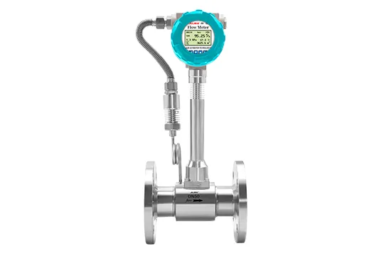
Short answer: a precession vortex flow meter measures gas volume by making the whole jet precess inside an expansion chamber. The precession frequency is proportional to flow, and built-in temperature and pressure sensors convert the result to standard volume. It is not a bluff-body vortex meter: it needs far less straight pipe and loses less pressure, which is why it dominates city-gas and low-pressure distribution metering.
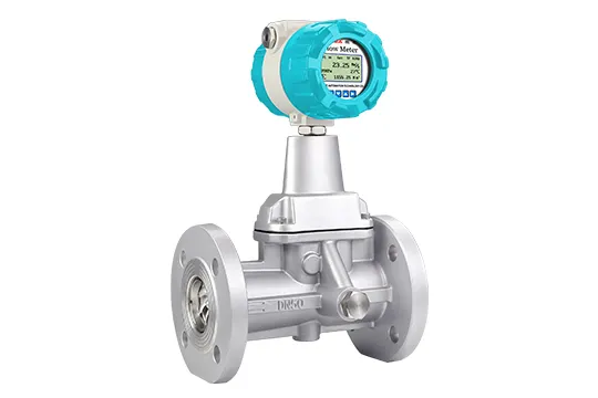
What the Meter Measures
Volumetric flow at line conditions, converted to a standard reference condition. Gas volume changes with pressure even when mass flow does not, so a meter reporting only cubic metres per hour at line conditions cannot support billing or day-to-day comparison. The converter reads pressure and temperature from the built-in sensors, applies the gas equation, and outputs standard volume. Whether that number is Nm3 or Sm3 depends on the reference condition written into your contract, and the two are not interchangeable.
If you need mass, multiply standard volume by density at the reference condition, or specify a thermal mass meter. The distinction matters more than it looks: two suppliers quoting the same pipe can be quoting numbers that differ by several percent purely because of the reference condition.
How the Precession Principle Works
Gas is accelerated through a tangential jet into a short expansion chamber. The jet does not shed vortices from a fixed bluff body; it precesses, spiralling around the chamber axis. The frequency of that precession is proportional to volumetric flow, which is the same relationship a vortex meter uses, obtained from a different geometry.
Two sensors on the chamber wall detect the pressure oscillation and the converter converts frequency to flow. Because the jet itself is the flow element, there is no bluff body to erode, no moving part to wear and no obstruction in the bore.
Vibration is the practical enemy. A precession signal is small, and a vibrating skid can look like flow. Meters in this family apply a vibration-rejection algorithm, but installation still decides the outcome: keep the meter away from compressors, regulators and pump discharge, and use the manufacturer bracket rather than a fabricated stand.
Precession Vortex vs Standard Vortex
| Item | Precession vortex | Standard vortex (bluff body) |
|---|
| Flow element | Swirling jet in an expansion chamber | Bluff body with vortex shedding |
| Typical medium | Natural gas, coal gas, compressed air, low-pressure gas | Steam, gas, liquids |
| Straight run | Short, typically about 5D upstream and 3D downstream | Long, typically 15 to 20D upstream and 5D downstream |
| Pressure loss | Lower, no bluff body in the flow path | Higher, the bluff body sits in the stream |
| Low-flow behaviour | Wider turndown, better on unstable low-pressure gas | Limited by the minimum Reynolds number |
| Typical duty | City gas distribution, trade metering, burner supply | Steam headers, utility gas, liquids |
The straight-run figures are typical of the type rather than a guarantee for every bore; confirm them against the manual for the size you order. The unit traps that catch gas projects are worked through in the gas flow meter selection guide.
Precession Vortex vs Other Gas Meters
| Meter | Strength | Weakness |
|---|
| Turbine gas meter | High accuracy, established for clean gas | Bearings wear; sensitive to dirt and to over-speed |
| Thermal mass meter | Direct mass flow, excellent at low flow and small bore | Gas-specific calibration; limited pressure and temperature headroom |
| Rotary (positive displacement) | Accurate at very low flow, no straight run needed | Moving parts, filtration essential, larger pressure loss |
| Orifice plate | Cheap, no power, simple to verify | High permanent pressure loss, narrow turndown |
Models and Specifications
Two bodies cover most duties. The aluminium alloy version is the cost-effective choice for clean, non-corrosive gas; the stainless steel version adds 304 or 316L wetted parts for mildly corrosive industrial gas.
| Parameter | Aluminium alloy | Stainless steel |
|---|
| Body material | Cast aluminium alloy | SS304 or SS316L |
| Nominal diameter | DN15 to DN200 | DN15 to DN200 |
| Accuracy | Class 1.0, Class 1.5 | Class 1.0, Class 1.5 |
| Nominal pressure | 1.6, 2.5, 4.0, 6.3 MPa | 1.6, 2.5, 4.0, 6.3 MPa |
| Medium temperature | -20 to 120 C; -20 to 180 C; -20 to 280 C | -20 to 120 C; -20 to 180 C; -20 to 280 C |
| Measured medium | Natural gas, coal gas, compressed air | Natural gas, coal gas, compressed air |
| Output | Pulse, 4-20 mA, RS485 Modbus | Pulse, 4-20 mA, RS485 Modbus |
| Power supply | 3.6 V lithium battery or 24 VDC | 3.6 V lithium battery or 24 VDC |
| Protection | IP65 | IP65 |
Explosion-proof marking differs between converters in this family. Confirm the exact marking against your zone and your market on the data sheet for the model you order rather than relying on a catalogue headline.
Sizing: Velocity Decides the Bore
Bore selection is a velocity decision. Four numbers fix it: the minimum, normal and maximum flow in Nm3/h; the operating pressure; the operating temperature; and the gas composition or relative density. From those, the bore, the velocity at each flow point and the pressure loss at maximum flow follow.
The most common sizing error is choosing the bore from the maximum flow alone. That is how a meter ends up running in the bottom few percent of its range, where the signal is weakest and the turndown claim is doing all the work. Size on the minimum: if the minimum flow cannot be measured, a larger bore is the wrong answer, not a better one.
Installation
Short straight run is the reason this meter gets specified, but short is not zero. Plan for about 5D upstream and 3D downstream, keep valves, reducers and double bends out of the upstream run, and make sure the pipe is full. The meter can be mounted horizontally or vertically; the converter head rotates so the display stays readable. On hazardous-area installations the body must be grounded per the certificate, and the cable entries must match the IP rating of the enclosure.
Accuracy and the Reference Condition Trap
Class 1.0 and Class 1.5 describe the error band over the specified flow range, not a constant offset. Two things erode the class in service: operating outside the calibrated pressure and temperature window, and a reference condition that differs from the one used at calibration. Ask for the reference condition in writing, and ask whether the accuracy figure includes the temperature and pressure sensors or only the flow element.
Where It Is the Wrong Choice
| Duty | Why it fails | What to use instead |
|---|
| Steam | These models are gas meters; the temperature and the two-phase behaviour are outside the design | Standard vortex meter with the matching rating, or orifice |
| Wet or dirty gas | Liquid slugs disturb the precession; deposits shift the chamber geometry | Turbine with filtration, or rotary |
| Pulsating flow from a reciprocating compressor | The signal is frequency-based; pulsation is indistinguishable from flow | Thermal mass, or add a pulsation damper upstream |
| Large bore at very low flow | Velocity falls under the measurable threshold | Smaller bore, or a thermal mass meter |
What to Send for a Quote
- Gas and composition, or at least relative density.
- Minimum, normal and maximum flow, and the unit you work in.
- Operating pressure and the pressure range.
- Operating temperature and ambient conditions.
- Pipe size, flange standard and the straight run available.
- Outputs required: pulse, 4-20 mA, RS485, battery or external power.
- Hazardous-area zone and the certification scheme your market requires.
FAQ
Is a precession vortex flow meter the same as a vortex flow meter?
No. A standard vortex meter sheds vortices from a bluff body and needs long straight runs; a precession vortex meter swirls the jet inside an expansion chamber, needs much shorter runs and handles low-pressure gas better. They are different flow elements and are not interchangeable.
Does it measure Nm3 or m3?
It measures volume at line conditions and converts to a standard reference condition using the built-in temperature and pressure sensors. Whether the result is labelled Nm3 or Sm3 depends on the reference condition in your contract, and those definitions are not the same across markets.
Can it measure steam?
Not these models. They are gas meters for natural gas, coal gas and compressed air. Steam needs a standard vortex meter with the matching temperature rating, or an orifice or Coriolis solution.
How much straight pipe is required?
Around 5D upstream and 3D downstream in typical installations, against 15 to 20D and 5D for a bluff-body vortex meter. Keep the upstream run free of valves, reducers and double bends, and confirm the final figure against the manual for your bore.
Can it be installed vertically?
Yes, horizontal and vertical mounting are both used, and the converter head rotates for readability. The pipe must stay full and the flow direction must match the arrow on the body.
What is the difference between Class 1.0 and Class 1.5?
The error band over the specified flow range: Class 1.0 is tighter. Ask whether the figure covers the flow element alone or includes the temperature and pressure sensors, because that changes what you actually get in service.
Next Step
Send the seven items above and we will return the bore, the velocity at each flow point and the pressure loss at maximum flow. The two body materials and their specifications are listed on the precession vortex flow meter range, and the wider gas question is covered in the gas flow meter selection guide.
Ethan Liu
Ethan Liu is JUJEA's technical content specialist, translating complex sensor integration and industrial automation concepts into practical insights for engineers, system integrators, procurement professionals, and decision-makers worldwide.


 한국어
 français
 Deutsch
 Español
 italiano
 русский
 português
 العربية
 tiếng việt
 čeština