Short answer: the 76-81 GHz radar is a non-contact level sensor that transmits a frequency-modulated continuous wave and reads distance from the beat frequency of the reflected echo. The 5 GHz sweep gives it a theoretical range resolution of about 3 cm, the 3 degree lens antenna keeps the beam off internal structures, and the 0.08 m blind zone lets it measure into the top of small tanks. This page condenses the 24-page manual into what a commissioning engineer needs: specifications, mounting constraints, wiring, the four menus and the echo curve reading.
What the Instrument Measures
Level, described three ways depending on the display mode: the level itself (distance from the vessel bottom or datum), the air gap (distance from the flange down to the product), or a percentage of the configured span. The sensor always measures the air gap first; everything else is derived from the reference point you set. That is why a wrong Sensor Offset or a wrong datum produces a constant error that looks like a calibration problem but is a setup problem.
The same head measures liquids, slurries, and solids such as powders, granules and blocks. It is not affected by the medium in the way a contact probe is, because nothing touches the product.
Specifications
| Parameter | Value |
|---|
| Transmit frequency | 76-81 GHz FMCW, 5 GHz sweep bandwidth |
| Measuring range | 0.08 to 120 m |
| Accuracy | +/-1 mm (specification table) |
| Beam angle | 3 degrees (DN50 flange and below), 8 degrees (DN80 and above) |
| Dielectric constant | 2 or higher |
| Power supply | 18-28 VDC, under 1 W, or 220 VAC |
| Output | 4-20 mA with HART, or RS485 with Modbus |
| Fault output | 3.6 mA, 22 mA, or hold the last value |
| Display | 128 x 64 dot matrix LCD, four keys |
| Housing | Aluminium alloy or stainless steel |
| Antenna | Lens antenna; shield, anti-corrosion, heat sink and quartz isolation flange options |
| Process pressure | -0.1 to 4 MPa |
| Ambient | -40 to 85 degrees C, 95 percent RH or less |
| Protection | IP68 |
| Cable entry | M20 x 1.5 or NPT 1/2 inch |
| Recommended cable | AWG18 or 0.75 mm2 |
| Dimensions | Diameter 100 mm, 270 mm long |
| Weight | 2.480 kg net, 2.995 kg gross |
| Mounting | Thread or flange |
What the Bandwidth Actually Buys
Range resolution is set by the sweep bandwidth: the manual gives the minimum distance resolution as c divided by two times B, which with B = 5.1 GHz works out to about 3 cm. Two reflecting surfaces closer together than that cannot be separated, and the instrument will report a single distance that belongs to neither of them. In a tank with a stirrer blade a few centimetres below the surface, that is the mechanism behind a reading that drifts between two plausible values.
The antenna angle matters more in practice. A 3 degree cone at 100 m covers a circle with a radius of roughly 2.6 m, so a 3 degree antenna at the top of a tall silo still only looks at a narrow column - which is exactly what keeps ladders, brackets and the filling stream out of the beam.
Installation Rules the Manual Insists On
Four constraints decide whether the meter works, and none of them can be corrected after the fact by parameters:
| Rule | Why it matters |
|---|
| No obstruction between the antenna face and the product | Ladders, limit switches, heating coils and brackets inside the 3 degree cone produce a fixed false echo that the level signal has to compete with |
| Beam must not cross the filling stream | The incoming material or its falling curtain reflects the pulse before it reaches the surface |
| Mount at 1/4 to 1/6 of the vessel diameter, at least 200 mm from the wall | Closer to the wall produces strong wall echoes and a false reading near the bottom |
| Highest level must stay outside the 0.08 m blind zone | Inside the blind zone the instrument has no usable echo at all |
For liquids the flange face must be horizontal - the antenna fires straight down. For solids the surface is usually inclined, and an inclined surface scatters the echo; the manual recommends a universal flange so the lens can be aimed perpendicular to the material surface, and the antenna must be kept clear of the feed port. Any installation where the vessel is empty and the geometry is fixed should have a False Echo learned on it before the first commissioning.
Wiring: Two-Wire or Four-Wire
| Version | Cable | Notes |
|---|
| 4-20 mA / HART, two-wire | One two-core shielded cable carrying both power and signal | Loop powered; 18-28 VDC at the terminals |
| 4-20 mA / HART or RS485, four-wire | Two two-core shielded cables, power separate from signal | Use where the loop cannot carry the consumption or where Modbus is required |
| Intrinsically safe version | As above plus a safety barrier | Barrier goes between the supply and the instrument |
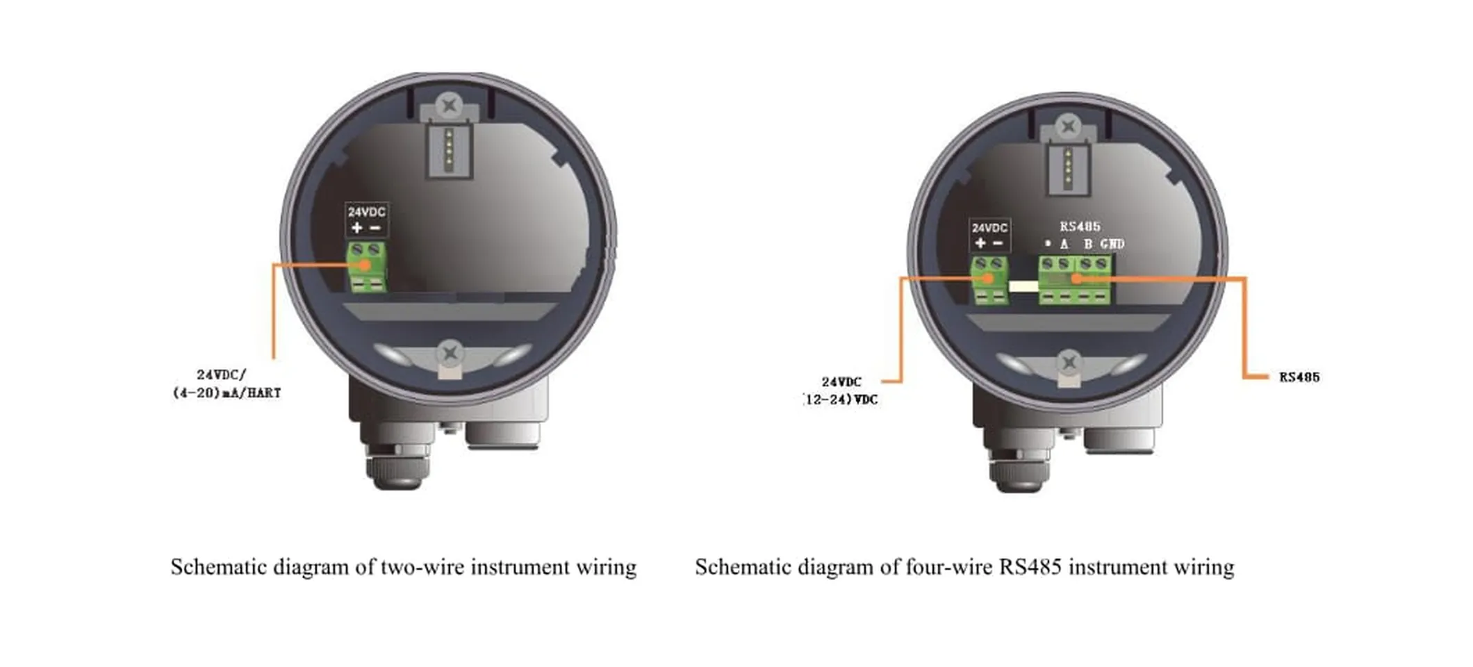
Terminals are marked 24VDC plus and minus for the supply, and A, B, GND for RS485. Cable entries are M20 x 1.5 or NPT 1/2 inch; 0.75 mm2 is the recommended conductor. On a four-wire unit the supply is labelled 12-24 VDC at the terminal block even though the specification table gives 18-28 VDC - check the nameplate on the unit in hand before connecting, and do not assume the terminal label is the full range.
The Four Keys and the Four Screen Modes
The display runs in Run mode, Echo mode, Setup mode and Input mode. In Run mode the OK key opens the parameter menu and BK jumps to the echo curve. In Echo mode the same keys switch back to Run, and one key toggles the threshold curve on and off. The reading screen shows level, the live loop current and, on the sample screen in the manual, the internal temperature.
The Echo Curve Is the Diagnostic
Press BK from the run screen and the instrument draws what it actually sees: echo amplitude against distance, with the threshold curve overlaid. The number at the top right is the maximum echo intensity in the range. The manual gives the reference points directly: a good metal reflector reads around 200 dB, and below 60 dB the echo is too weak to trust and the installation needs attention.
That single number separates the two failure modes that look identical on the display. A level that jumps while the intensity stays high is a false echo problem - something in the cone is reflecting. A level that drifts slowly while the intensity sags is a signal problem - foam, condensation on the lens, or a medium with a dielectric constant close to 2. Raise the threshold, learn a false echo, or change the antenna, but do not start by moving the range.
Basic Menu: Six Items That Must Be Right First
| Item | What it does | Set it to |
|---|
| High Low Calib | Maps measured value to the 4-20 mA output | High = full level, Low = empty level, in the display unit |
| Range | Echoes beyond this distance are ignored | Just above the maximum distance to the product |
| Deadband | Blind zone at the antenna | 0.08 m unless the application needs otherwise |
| Damping | Smooths the output; 2 s means a step settles in about 10 s | Long enough to calm a rippling surface, short enough for control |
| Media Type | Liquid or solid signal processing | Match the actual product |
| Vess Type | Vessel geometry preset | Match the tank or silo shape |
Advanced Menu: False Echo, Offset and Output Behaviour
| Item | Function |
|---|
| False Echo | Learns the fixed reflections in an empty vessel and builds a suppression curve; set start, end and intensity before learning |
| Sensor Offset | Corrects the difference between the ideal and actual reference; set at the factory, change only after a verified empty-tank check |
| Bus Address | Modbus address for RS485, or multipoint address for HART |
| Output Mode | 4-20 mA or 20-4 mA, i.e. which end the current rises towards |
| Current Sim | Trims the current output; factory calibrated |
| Current Func | What the loop does on echo loss: hold the last value, 22 mA, or 3.6 mA |
The Current Func choice is a control decision, not a preference: 22 mA drives most DCS high-level alarms, 3.6 mA drives failure alarms, and hold keeps the last good value so the loop does not trip on a momentary loss. Pick it before commissioning, because it also decides what the operator sees during a real fault.
Service Menu: Tuning When the Defaults Are Not Enough
| Item | Use it when |
|---|
| Echo Rate | Higher values make the waveform slower and steadier, lower values make it faster |
| Window Set | The echo is lost or the vessel fills and empties too fast to track; defines the search window and time around the locked echo |
| Echo Scale | Sets how much the echo must exceed the window percentage to be accepted |
| Echo Lock | Locks the search to the window, typically with an agitator; unlocked searches the whole range |
| 1st Filter | Short-range measurement environments |
| 2nd Filter | Long-range environments; should not be used if the blind zone is small |
| Response Rate | Tracking speed on rising level; solids slightly higher, liquids slightly lower |
| Threshold Set | Raises the amplitude an echo must reach, which suppresses small clutter |
Display Menu and the Export Detail Nobody Checks
Four items: display mode (level, air gap or percentage), units (m, cm, mm), language (Chinese or English) and LCD contrast. The sample screens in the manual show Chinese selected by default, so a unit shipped without this step arrives with a Chinese menu - set the language before dispatch, not on site.
Commissioning Sequence
In the order the manual implies, and in the order that avoids redoing work:
| Step | Action | Check |
|---|
| 1 | Confirm the vessel is empty and the geometry matches the drawing | Antenna perpendicular, level below the blind zone |
| 2 | Set units and language | Display readable |
| 3 | Enter Range and Deadband | Echo curve shows one strong peak inside the window |
| 4 | Select Media Type and Vess Type | Echo shape stable while filling |
| 5 | Learn False Echo with the vessel empty | Clutter peaks drop below the threshold |
| 6 | Set High Low Calib | 4 mA at empty, 20 mA at full, verified at both ends |
| 7 | Set Damping and Response Rate | No overshoot on a fast fill |
| 8 | Set Current Func and test it | Simulate echo loss and confirm the DCS reaction |
Two Places Where the Manual Contradicts Itself
The specification table gives +/-1 mm accuracy; the glossary at the back describes the same instrument as reaching 0.1 mm. Both statements are in the same document, and only the factory can say which figure the calibration certificate will carry - quote the specification table figure to a customer and confirm the certificate before a metrology application.
The second is the supply range: the specification table says 18-28 VDC, the wiring terminal block is labelled 12-24 VDC. Read the nameplate of the unit in hand rather than either figure.
FAQ
Can it measure powders and granules?
Yes. Solids are within the stated application range, provided the dielectric constant is 2 or higher and the antenna can be aimed perpendicular to the surface. A sloped or conical stockpile scatters the echo, which is why the manual specifies a universal flange for those silos.
What happens if the product comes up to the antenna?
Inside the 0.08 m blind zone there is no usable echo, so the output goes to whatever Current Func is set to. Either set the High Low Calib span to stop below the blind zone or mount the instrument higher.
Will dust or steam stop it?
The manual states the short wavelength penetrates dust, steam and foam with minimal attenuation, which is the main reason to choose this type over ultrasonic in a dusty silo. Condensation directly on the lens is a different problem and shows up as falling echo intensity, not as a frozen reading.
Do I need the heat sink antenna?
The series is described as suitable for harsh temperature environments up to 200 degrees C, and the heat sink antenna is the option for that range. Confirm the process temperature limit for the specific antenna variant before ordering for a high-temperature kiln or dryer.
Why is the reading offset by a constant amount?
Almost always the reference point. The instrument measures to the flange face; if the site expects level from the vessel bottom, the difference has to be entered as the offset or as the low calibration point. Check the empty reading before touching Sensor Offset.
Two-wire or four-wire?
Two-wire where the loop can supply the instrument and only 4-20 mA or HART is needed. Four-wire where Modbus RS485 is required or where the supply must be separate from the signal.
Download and Next Step
The full manual is on the download page: 80GHz Radar Level Meter Instruction Manual (PDF). The instrument range, antenna options and process connections are on the 80 GHz radar level meters page.
If the application is a tank with internal fittings, send the vessel drawing and the medium dielectric constant - the mounting position and the false echo setup depend on both.
Ethan Liu
Ethan Liu is JUJEA's technical content specialist, translating complex sensor integration and industrial automation concepts into practical insights for engineers, system integrators, procurement professionals, and decision-makers worldwide.


 한국어
 français
 Deutsch
 Español
 italiano
 русский
 português
 العربية
 tiếng việt
 čeština