Short answer: the F3000X is a panel-mount flow totalizer, not a sensor. It takes the signal from a flow transmitter - 4-20 mA, 0-10 mA, frequency, or a differential pressure transmitter - applies density compensation for gas, steam or natural gas, and produces flow rate, total, shift reports and relay alarms. This page condenses the 23-page manual into the tables you actually use at the panel: terminals, equations, compensation modes, parameter map and faults.
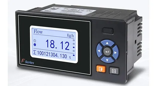
The nameplate on the instrument reads F3000X; the same unit is catalogued on this site as the GT30XF flow totalizer. The manual, the product page and this page describe one product, and spare parts are ordered by either code.
One thing worth stating before the tables: the quoted accuracy is the accuracy of the indicator, not of the flowmeter it is connected to. A Class 1.0 sensor fed into the F3000X is still a Class 1.0 measurement; the totalizer will not improve it, and the 0.2% figure only describes how faithfully the instrument reads its own input.
What the F3000X Does and Does Not Do
The instrument is built on an ARM Cortex-M3 core with a 128x64 monochrome LCD. It collects flow, temperature and pressure, computes the compensated result, displays four alternative screens (overview, parametric, bar-graph, signal debugging), and keeps shift, daily, monthly and annual totals. It also logs power-off events and alarms, and exports reports to a USB stick.
It is not a flow sensor, and it is not an explosion-proof instrument: the manual states it is prohibited in flammable or corrosive atmospheres, and it is intended for indoor panel mounting with 0-50 C ambient. If you need a field-mounted Ex-rated version, the sensor side has to be specified separately.
Specifications
| Item | Value |
|---|
| Display | 128x64 monochrome LCD |
| Accuracy (indicator) | plus or minus 0.2% F.S. |
| Processor | ARM Cortex-M3, 32-bit |
| Flow input | 0-10 mA, 4-20 mA, frequency 0-5000 Hz (Vil 1 V max, Vih 5 V min) |
| Temperature input | 0-10 mA, 4-20 mA, Pt100 |
| Pressure input | 0-10 mA, 4-20 mA |
| Sensor supply | 1 x 12 VDC (F12) and 2 x 24 VDC (Q24, P24), 30 mA max per channel |
| Current output | 1 channel, 4-20 mA, load 500 ohm max |
| Relay output | up to 3, 3 A at 250 VAC or 3 A at 30 VDC, HH / HI / LO / LL |
| Communication | RS485 and RS232C, Modbus RTU; RS232C print port |
| Report backup | USB 1.1 / 2.0, 1-32 GB stick |
| Power supply | 220 VAC 50 Hz; 24 VDC (18-36 V) or 12 VDC (9-18 V) on order |
| Clock error | plus or minus 2 s per day |
| Ambient | 0-50 C, 0-85% RH, altitude below 2000 m |
| Net weight | 1.0 kg or less |
Panel Cutout and Mounting
Bezel is 160 x 80 mm; the opening is 152 x 76 mm with a +1/0 mm tolerance. Panel thickness has to be between 1.5 and 6.5 mm. The meter is pushed through from the front, then held by two brackets with M4 screws, one on each side.
Two practical notes from the drawing: the minimum spacing between adjacent meters is set by heat dissipation, so do not butt them against each other in a dense panel; and the depth dimension on the manual drawing is labelled 750 mm, which is almost certainly a typo for 75 mm for a 160 x 80 case - measure the unit before you cut a deep enclosure.
Terminals
| Terminal | Function |
|---|
| L/+, N/-, ground, NC | AC phase and neutral, protective earth; DC positive and negative; NC spare |
| A+, B- | RS485 communication |
| R1~R2 | Relay outputs, 3 A at 250 VAC / 3 A at 30 VDC |
| F+, F-, F12 | Frequency flow input, with 12 VDC feed for the sensor |
| Q+, Q-, Q24 | Differential pressure transmitter input, with 24 VDC feed |
| AO+, AO- | Transmission current output |
| TA, TB, TC | Temperature channel (Pt100 three-wire or transmitter) |
| P+, P-, P24 | Pressure transmitter input, with 24 VDC feed |
| COM | RS232C / printer (pin 2 RXD, pin 3 TXD, pin 5 signal ground) |
| LAN | Ethernet RJ45 |
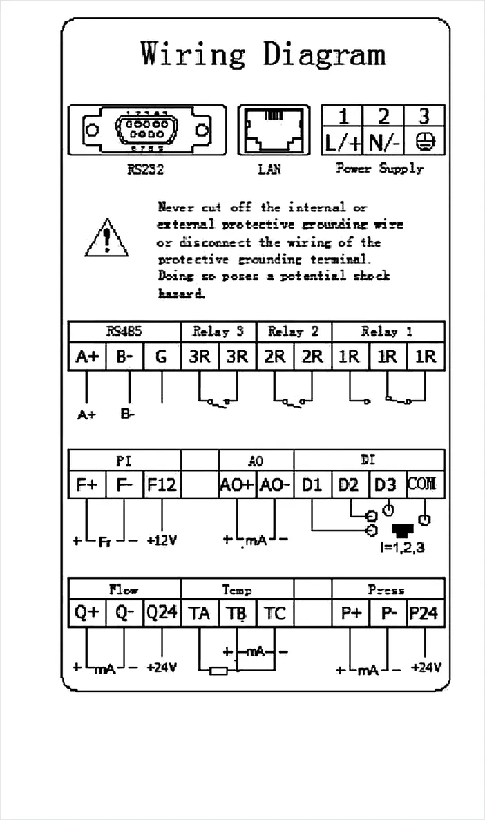
Four wiring rules carry most of the field failures: run the measuring circuit and the power circuit in separate trays; use shielded cable where electrostatic interference is present; keep each Pt100 lead under 10 ohm with all three leads equal; and never parallel a current signal or a thermal resistance with another instrument - the reading of both units will shift.
Flow Equations
| Mode | Equation | Use it with |
|---|
| DP (differential pressure) | Q = K x square root of (dP x density) | Orifice, Venturi, averaging pitot, wedge |
| Freque (frequency) | Q = 3600 x If x density / K | Turbine, vortex, positive displacement with pulse output |
| Linear (analog) | Q = K x density x dP | Electromagnetic, ultrasonic, thermal mass with 4-20 mA |
The mode decides what K means, and this is where most commissioning errors start. In frequency mode K is pulses per cubic metre taken from the sensor certificate; in DP mode it is the flow coefficient derived from the orifice bore, and the square-root extraction is applied locally unless the transmitter already does it.
Medium Compensation
| Setting | What it does | Output |
|---|
| DisComp | No compensation; density fixed at 1000 kg/m3 | Volume at line conditions |
| GAS | Ideal gas law, converts to standard condition | Standard volume |
| SHS | Saturated steam density from pressure or temperature | Mass flow |
| STS | Superheated steam density from pressure and temperature | Mass flow |
| Natgas | Ideal gas law with compressibility factors Zn and Zf | Standard volume |
For GAS and Natgas the instrument uses a reference temperature of 20.00 C and a reference pressure of 0.000 MPa gauge. That single setting decides what the word normal means on your reports: a site that contracts at 0 C will show roughly 6.8% less volume for the same mass flow, so agree the reference condition before the first invoice, not after.
Steam modes work from the built-in steam table: SHS looks up density from pressure or temperature, STS needs both. If you are totalizing steam for cost allocation, the dryness assumption is the larger error source than the totalizer - see our steam flow meter selection guide.
Parameter Map
| Menu | What sits inside |
|---|
| Sys | Time, password, cycle time, atmospheric pressure, system maintenance (clear power-off list, clear alarm list, restore defaults) |
| Flow | Mode, unit, range, K factor, filter time, low cut, medium and compensation, cumulative unit, shift start and duration, cumulative preset, clear |
| Temp / Pres | External or fixed value; Pt100 or 4-20 mA; range and offset |
| Output | Current output type, direct or reverse action, range, signal source channel |
| ALM | HH, HI, LO, LL thresholds, relay assignment, dead band, cumulative alarm |
| Comm | PC or printer mode, address 1-255, baud rate, parity, stop bits |
Login, Keys and the One Setting to Change First
Hold Menu and Enter together for about one second to reach the configuration screen. The default password is 00 00 00 for both operator and administrator levels. Change it on day one: the same password unlocks the K factor, the compensation mode and the totals, and there is no separate audit trail for parameter edits.
Also treat system maintenance as destructive: clearing the power-off list or restoring factory defaults wipes historical data, the alarm list and the totals, and the action cannot be undone.
Communication
RS485 uses A+ and B- with G for signal ground, 120 ohm termination at both ends of the bus, addresses from 1 to 255 and no duplicates. Defaults are odd parity and 2 stop bits, which is the opposite of what many PLC projects assume - check parity before you conclude the converter is faulty.
Baud rate is stated three different ways in the manual: the specification chapter lists 1200, 2400, 4800 and 9600; the communication chapter lists 1200, 4800 and 9600; the configuration screen in the illustration shows 19200. Read the value the actual unit displays rather than the value in the PDF.
Reports and USB Backup
Shift, daily, monthly and annual totals are kept separately, with a configurable shift start between 0 and 11 o'clock and a shift length of 8 or 12 hours. Reports export to a FAT32 USB stick of 1 to 32 GB. If the file is empty, the usual cause is a record interval longer than the period you selected, or a stick formatted as NTFS.
Fault Table
| Symptom | Cause | Action |
|---|
| No power | Poor contact at the power terminal, switch not closed | Check supply and terminal screws |
| Display does not match the process | Signal type set wrongly, wiring error | Check configuration against the transmitter, then the signal line |
| Relay acts at the wrong point | Alarm threshold or relay assignment wrong; points shared between channels | Reset threshold, remove shared assignments |
| Sensor supply problem | Too many transmitters drawing from the internal supply, digital and analog interference | Use an external stabilised supply, separate the supplies |
| USB transfer fails | Wrong start or end time, wrong format, incompatible stick, full stick | Set the time range, format FAT32, use a compatible stick |
| USB file empty or abnormal | No data in the selected period, system time changed, record interval too long | Select a period with data, keep the time stable, shorten the interval |
| Current output wrong | Signal source or range mismatch | Check the source channel and the 4-20 mA range |
Packing List
One totalizer, two mounting brackets with M4 screws, one printed manual, one quality certificate and warranty card. The RS232C/RS485 conversion module and the RS232C cable are optional items and are not in the box unless ordered.
FAQ
Does the F3000X power the transmitter?
Yes. It provides one 12 VDC output (F12) and two 24 VDC outputs (Q24, P24), each limited to 30 mA. That is enough for a standard two-wire transmitter and not enough for a loop-powered device with a heater, a display backlight or a second output; above that, feed the sensor from an external supply and use the terminals for signal only.
Can it totalize steam?
Yes, in SHS or STS mode, and the output becomes mass flow rather than volume. You need a working pressure or temperature input, because the density comes from the steam table rather than from a fixed value.
Is 0.2% the accuracy of the measurement?
No. It is the accuracy of the indicator reading its own input. The measurement accuracy is set by the flow sensor and by how well K matches the actual pipe and medium.
Can I connect an electromagnetic flowmeter to it?
Yes, in Linear mode with a 4-20 mA input. The totalizer then adds compensation, totals, reports and alarms to a meter that already outputs volume.
Why does my total differ from the PLC total?
Three usual reasons: a different reference condition for normal volume, a different low-flow cut-off, or a different K factor rounding. Compare the reference temperature and the cut percentage first.
Does it support Modbus RTU?
Yes, over RS485 or RS232C, with addresses 1 to 255. Set the same baud rate and parity on both sides - the factory defaults are not the most common PLC defaults.
Download and Next Step
The full 23-page manual, including the dimension drawing and the wiring schematic, is available as a PDF: F3000X Flow Totalizer Manual (PDF).
The instrument itself, with the ordering code and the panel-mount options, is on the GT30XF flow totalizer product page. If the totalizer is being specified with a sensor, the matching pages are the vortex flow meters with temperature and pressure compensation and the steam flow meter selection guide. Send us the sensor certificate, the medium and the reference condition, and we will return a parameter list for the panel.
Ethan Liu
Ethan Liu is JUJEA's technical content specialist, translating complex sensor integration and industrial automation concepts into practical insights for engineers, system integrators, procurement professionals, and decision-makers worldwide.


 한국어
 français
 Deutsch
 Español
 italiano
 русский
 português
 العربية
 tiếng việt
 čeština