Monitoring liquid levels in groundwater wells and industrial storage tanks requires instruments that can operate reliably under different installation conditions. Narrow well casings, groundwater fluctuations, sediment deposits, long cables, and nearby pump equipment create challenges that are less common in accessible storage tanks.
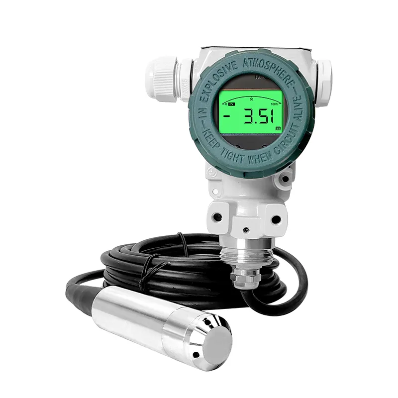
A submersible level transmitter measures hydrostatic pressure through a probe immersed in the liquid. It provides continuous level information without requiring an instrument above the liquid surface to detect reflections.
Successful operation depends on the measuring range, probe placement, liquid compatibility, cable protection, and environmental conditions. For water wells, these details are particularly important because maintenance access may be limited.
How Does a Submersible Level Transmitter Measure Liquid Level?
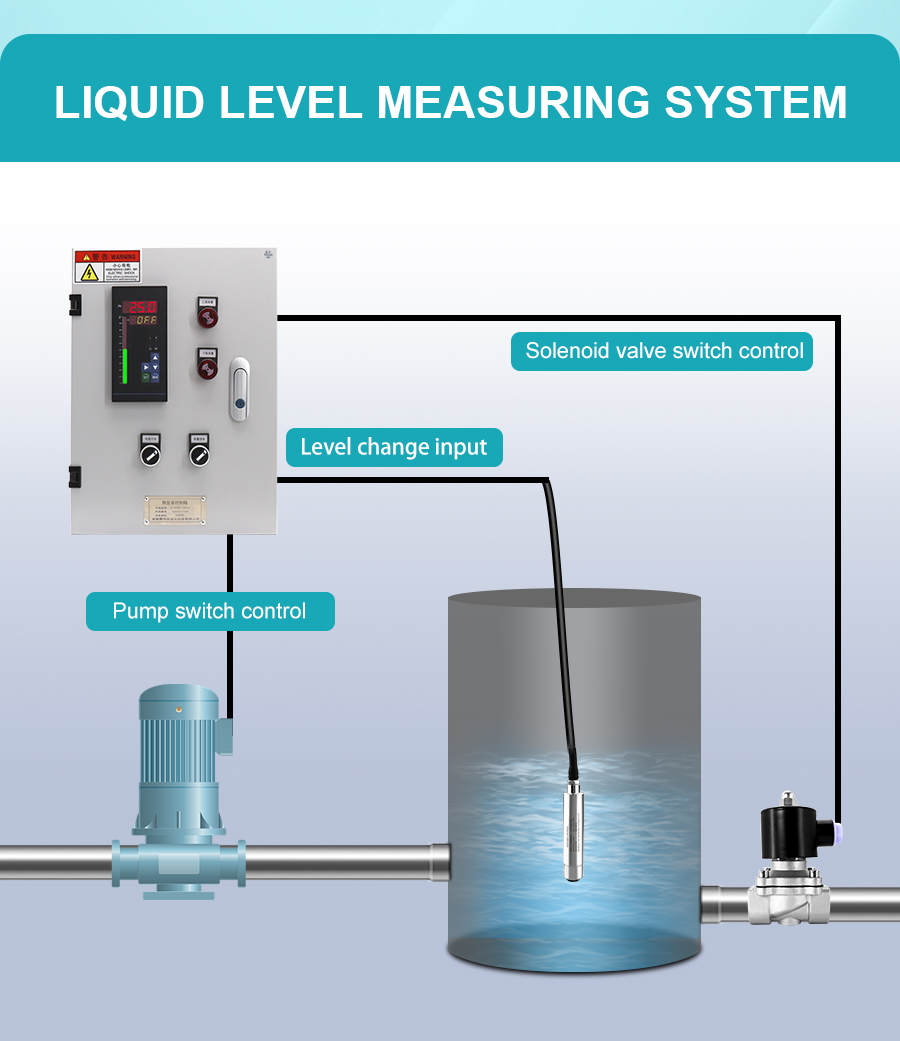
A submersible level transmitter measures the hydrostatic pressure generated by the liquid column above its sensing point.
The instrument converts this pressure into a level-related output using an appropriate calibration and pressure reference. In an open well or atmospheric tank, the measurement can represent the water height above the probe.
The reading is not automatically the total well depth. Engineers must record the probe's installation elevation and use a consistent reference point when interpreting groundwater level.
Liquid density and pressure-reference design also affect measurement results. A vented gauge-pressure transmitter may use an atmospheric reference through its cable, while other designs use different arrangements.
Because the sensing element remains submerged, long-term compatibility with the liquid and installation environment must be considered.
Water Wells vs. Storage Tanks: What Changes During Installation?
Although wells and tanks can use the same hydrostatic measuring principle, their installation constraints differ.
Water wells often require long suspension cables, compact probe dimensions, and careful positioning around the pump and rising main. A storage tank may allow easier access but introduce agitation, chemical exposure, or process deposits.
| Installation Factor | Water Well | Storage Tank |
|---|
| Installation space | Narrow casing and limited clearance | Usually more accessible |
| Level variation | Groundwater recharge and pumping drawdown | Filling and emptying cycles |
| Common deposits | Sand, silt, and mineral scale | Sludge or process residues |
| Probe positioning | Clear of pump and sediment | Clear of deposits and obstructions |
| Cable arrangement | Long protected suspension | Depends on tank height |
| Maintenance access | Often restricted | Generally easier |
In a well, the probe should remain submerged throughout the intended measuring range without obstructing pump maintenance.
The vertical rising pipe normally carries water from the pump toward the discharge system. It should not be confused with the location of the hydrostatic level probe.
Engineers should confirm the available casing clearance, mounting point, and retrieval route before selecting the probe size and cable length.
How Do Sediment, Mineral Scale and VFD Interference Affect Reliability?
Sediment and mineral scaling create different maintenance problems.
Sediment consists of particles such as sand and silt. If the probe is positioned too close to the well bottom, these particles may accumulate around the sensing port or eventually bury the instrument.
Mineral scale forms when dissolved minerals deposit on exposed surfaces. Depending on groundwater chemistry, deposits may build up on the probe and affect long-term measurement reliability.
Sediment risk is managed primarily through suitable probe positioning and periodic inspection. Scaling requires assessment of water chemistry and an approved cleaning procedure compatible with the sensing materials.
Variable-frequency drives (VFDs) introduce another potential problem. Their motor circuits can generate electrical interference that affects nearby instrument signals.
To reduce interference, engineers should separate signal cables from VFD motor cables and follow the transmitter manufacturer's shielding, grounding, and surge-protection instructions.
A fluctuating level signal should be checked against actual water-level behavior before being attributed to VFD interference or sensor malfunction.
Why Do Cable Construction and Pressure Referencing Matter?
Many submersible gauge-pressure transmitters use a vented cable to maintain an atmospheric pressure reference.
Where this design is used, the vent must remain protected from water intrusion and blockage. A blocked vent can introduce measurement errors even when the submerged probe is otherwise functioning.
Cable protection is particularly important in narrow wells, where a long suspended cable may contact the casing or nearby pump equipment.
Installation checks should include mechanical strain relief, suitable bend radius, moisture protection, and safe routing through the wellhead.
Not every submersible level transmitter has the same pressure-reference design. The selected model's instructions should determine whether a vented cable is necessary and how its termination must be protected.
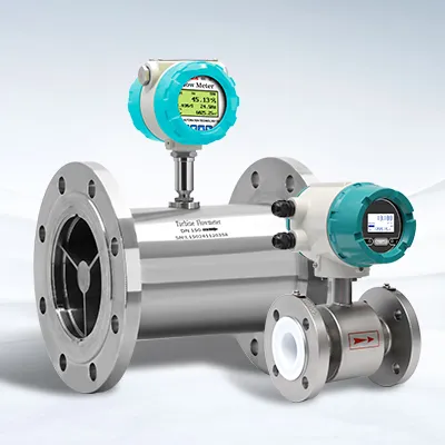
How Does Well Level Monitoring Work with Flow and Energy Data?
Water level measurement is one part of a wider well-monitoring system.
The submersible transmitter records groundwater level changes, while a separate flow meter measures water delivered through the discharge pipeline.
Two installation considerations belong to the flow meter, rather than the submersible level transmitter.
First, a freely discharging pipe may be partially filled near its outlet. If the chosen flow meter requires a full pipe, its installation location must satisfy that condition.
Second, a vertical rising discharge pipe can be considered as a measuring location where the flow meter's full-pipe, straight-run, and accessibility requirements are met.
Combining level, flow, and electrical energy records can help operators assess pumping-system operation.
For energy reporting, use the consistent term Specific Energy Consumption (SEC), expressed in kWh/m³. It describes the electrical energy consumed per cubic meter of delivered water.
SEC requires both electrical energy and measured water volume. It is not an output measured directly by the submersible level transmitter.
Which Technical Specifications Should Buyers Confirm?
JUJEA offers submersible level transmitters for groundwater wells, storage tanks, wastewater treatment, and other compatible liquid-level applications. The product range includes 304 stainless steel and PTFE configurations for different measurement environments.
The following specifications are provided in JUJEA's published product information.
| Technical Parameter | JUJEA Submersible Level Transmitter Specification |
|---|
| Product configurations | 304 Stainless Steel Submersible Level Meter; PTFE Submersible Level Meter |
| Measuring medium | Stainless steel: various water, oil, acid-base, high-temperature liquids; PTFE: strong corrosive liquids such as sulfuric acid, hydrochloric acid |
| Wetted materials | Stainless steel: Diaphragm: 316L stainless steel Housing: 304 stainless steel; PTFE: ceramic chip PTFE housing |
| Measuring range | 0~200 m |
| Measuring method | Submersible measurement |
| Accuracy class | 0.5% |
| Power supply | 24VDC |
| Load resistance | <500Ω |
| Thermal zero drift | <0.03% F.S/℃ |
| Output signal | 4–20 mA |
| Ambient humidity | 0–95% |
| Medium temperature | 0-100℃ (custom gas-collecting pressure tube) |
| Operating temperature | −10~80°C |
Specifications are based on JUJEA's published Submersible Level Transmitters specification table. Actual material compatibility, available configurations, and operating limits should be confirmed for the selected model.
For groundwater well installations, engineers should also confirm the probe diameter, cable length, pressure-reference design, sediment conditions, and required immersion depth.
For storage tanks containing corrosive liquids, the PTFE configuration should be evaluated against the actual chemical concentration, temperature, and operating conditions.
Before ordering, provide the measuring range, liquid properties, installation depth, cable requirements, and desired output signal to JUJEA for model confirmation.
Conclusion
Submersible level transmitters provide continuous hydrostatic monitoring for groundwater wells and compatible storage tanks. Their reliability depends on correct probe positioning, measuring range, pressure referencing, cable protection, and wetted-material compatibility. Well installations require additional attention to sediment burial, mineral scaling, narrow casing clearance, and possible VFD interference. Flow and energy monitoring can complement level measurements, but those functions require separate instruments. JUJEA offers submersible level measurement products for industrial applications. Engineers should confirm the selected model's technical specifications and establish suitable installation and maintenance procedures before commissioning.
Frequently Asked Questions
Can a submersible level transmitter monitor groundwater during pumping?
Yes, provided the probe remains properly submerged and installed under suitable measurement conditions.
Can a VFD cause unstable level readings?
Electrical interference is possible in some installations. Cable routing, shielding, grounding, and actual water-level changes should be checked.
Is mineral scaling the same as sediment accumulation?
No. Scaling involves mineral deposits, while sediment consists of particles such as sand and silt.
Can a submersible level transmitter measure flow in a vertical discharge pipe?
No. It measures liquid level. Pipeline flow measurement requires a separate instrument.
Does every submersible transmitter require a vented cable?
No. Pressure-reference arrangements depend on the transmitter design.
What information should buyers provide before ordering?
Provide installation depth, measuring range, casing or tank dimensions, liquid properties, sediment conditions, cable requirements, and the required monitoring interface.
Ethan Liu
Ethan Liu is JUJEA's technical content specialist, translating complex sensor integration and industrial automation concepts into practical insights for engineers, system integrators, procurement professionals, and decision-makers worldwide.


 한국어
 français
 Deutsch
 Español
 italiano
 русский
 português
 العربية
 tiếng việt
 čeština